2.2 Button Debounce
The goal of this example is to show you how to make button presses more reliable and consistent by using a technique called debouncing.
When we press a physical button, its contacts can bounce rapidly, causing the microcontroller to detect multiple presses instead of one.
In this example, we’ll use software debouncing with the millis() function to ensure that one press equals one toggle of the LED.
In this documentation you will learn:
- How to read a button state with
digitalRead(). - What is button debouncing and how to handle it with
millis(). - How to toggle an LED on each button press.
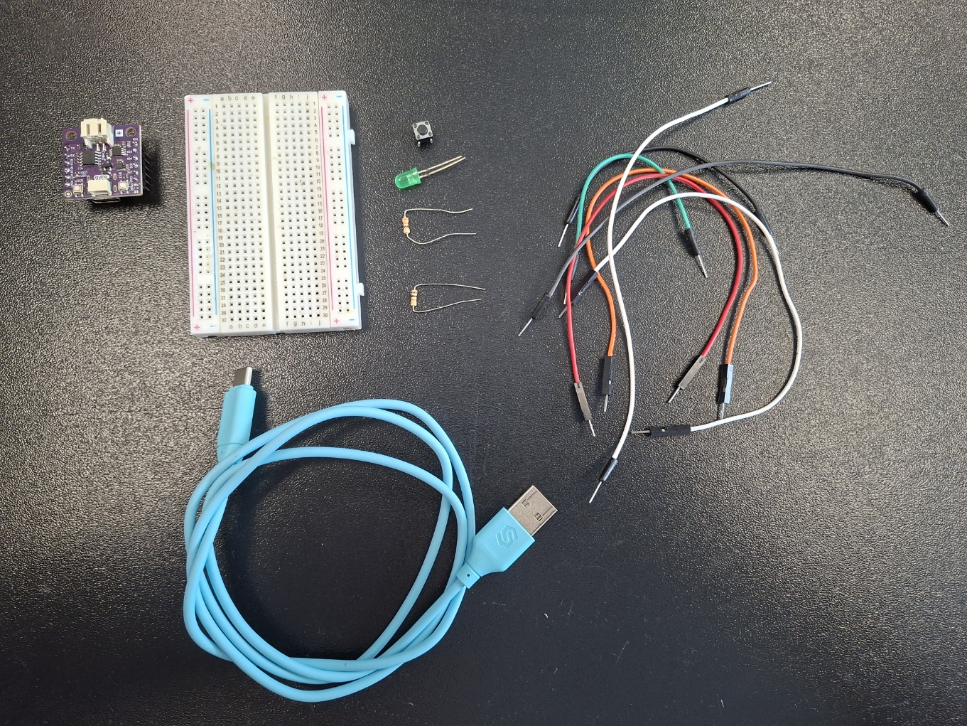
Hardware required:
- 1x Soldered NULA MINI board
- 1x Breadboard
- 1x Push button
- 1x LED (any color)
- 1x 330 ohm resistor
- 1x 10k ohm resistor
- Jumper wires
- USB-c cable
Putting the components together
We will start this example by connecting all the components. Just follow the steps provided below for a no hassle experience.
1. insert the NULA MINI board on the breadboard
If your board has male connectors soldered to its pins, we recommend placing it on the breadboard to make it easier and tidyer for yourself to connect other components.
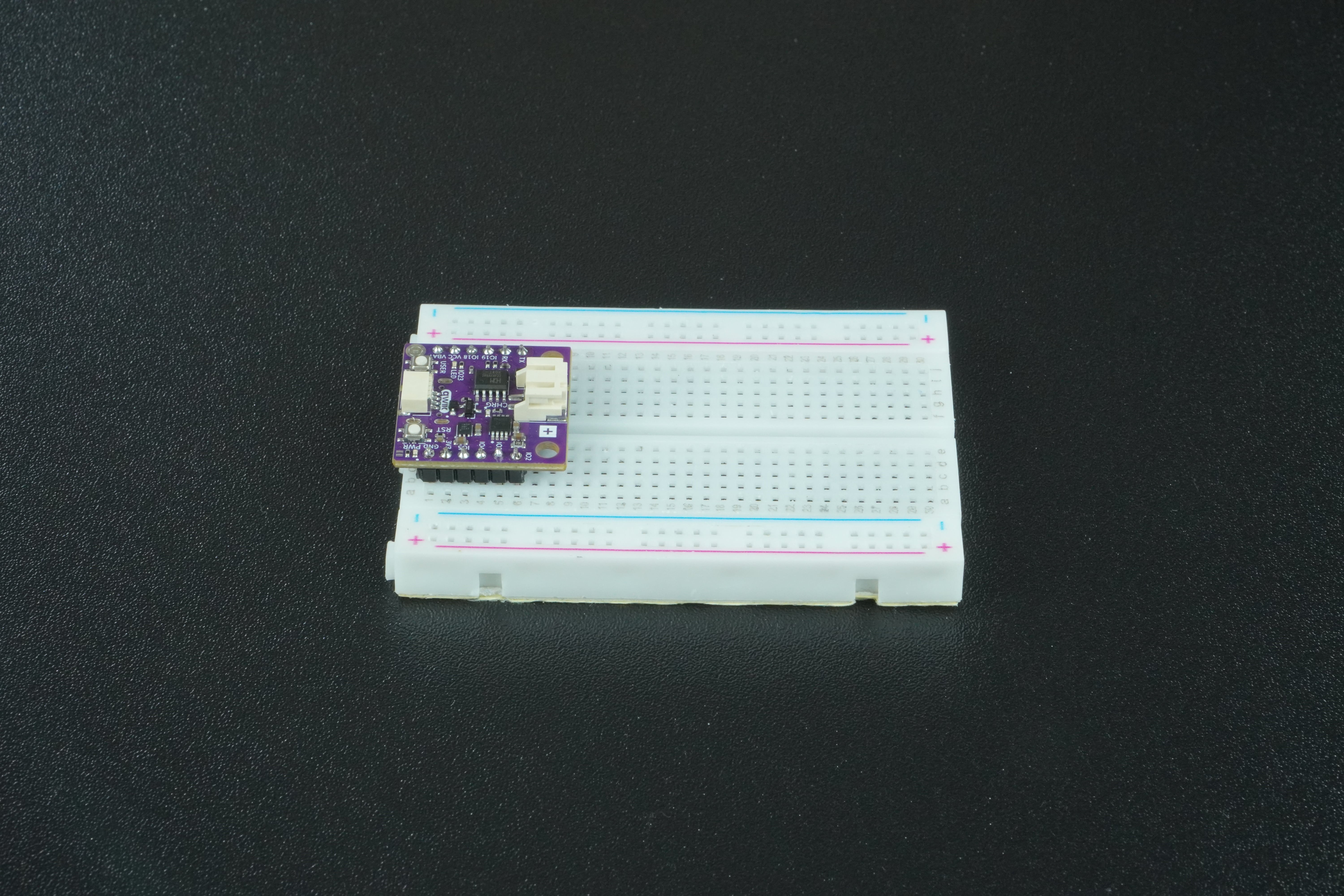
If not, no worry. You can just connect the board with components by wire. It will be a bit messier but will do the job just fine.
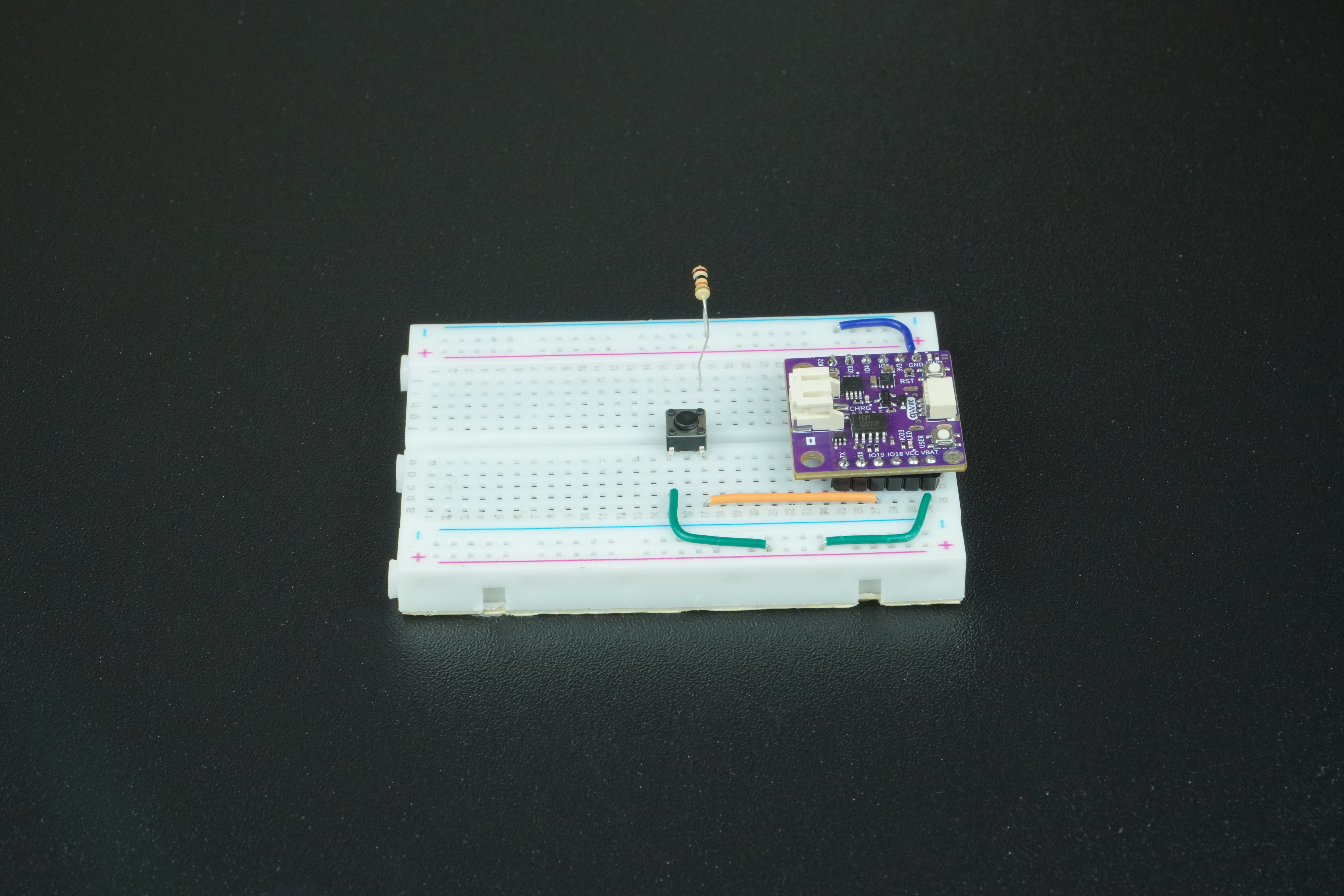
2. Connect the Push button to the NULA MINI board
Using a jumper wire, connect IO19 on the NULA MINI to one leg of the push button on the breadboard. Connect the opposite leg of the button to GND through a 10kΩ resistor, and also connect that same leg to 3.3V. Your completed circuit should look like this:
What is a Pull-Down Resistor?
When you connect a button directly to a pin on the NULA MINI board, the pin doesn’t always know if it should read as HIGH or LOW when the button is not pressed. In that “floating” state, the pin can randomly pick up electrical noise and switch between HIGH and LOW by itself, which leads to unreliable behavior.
A pull-down resistor fixes this by gently “pulling” the pin’s value down to LOW (0V) whenever the button is not pressed. Think of it like a spring that always pulls the pin back to ground level when nothing else is happening.
- When the button is not pressed, the resistor connects the pin to GND, so the NULA board reads LOW.
- When the button is pressed, the button connects the pin directly to 3.3V, and the board reads HIGH.
The resistor value (commonly 10kΩ) is chosen so it’s strong enough to keep the pin LOW when idle, but weak enough not to interfere when the button is pressed.
Without a pull-down resistor, your button input may behave unpredictably, sometimes showing HIGH even when you are not pressing it.
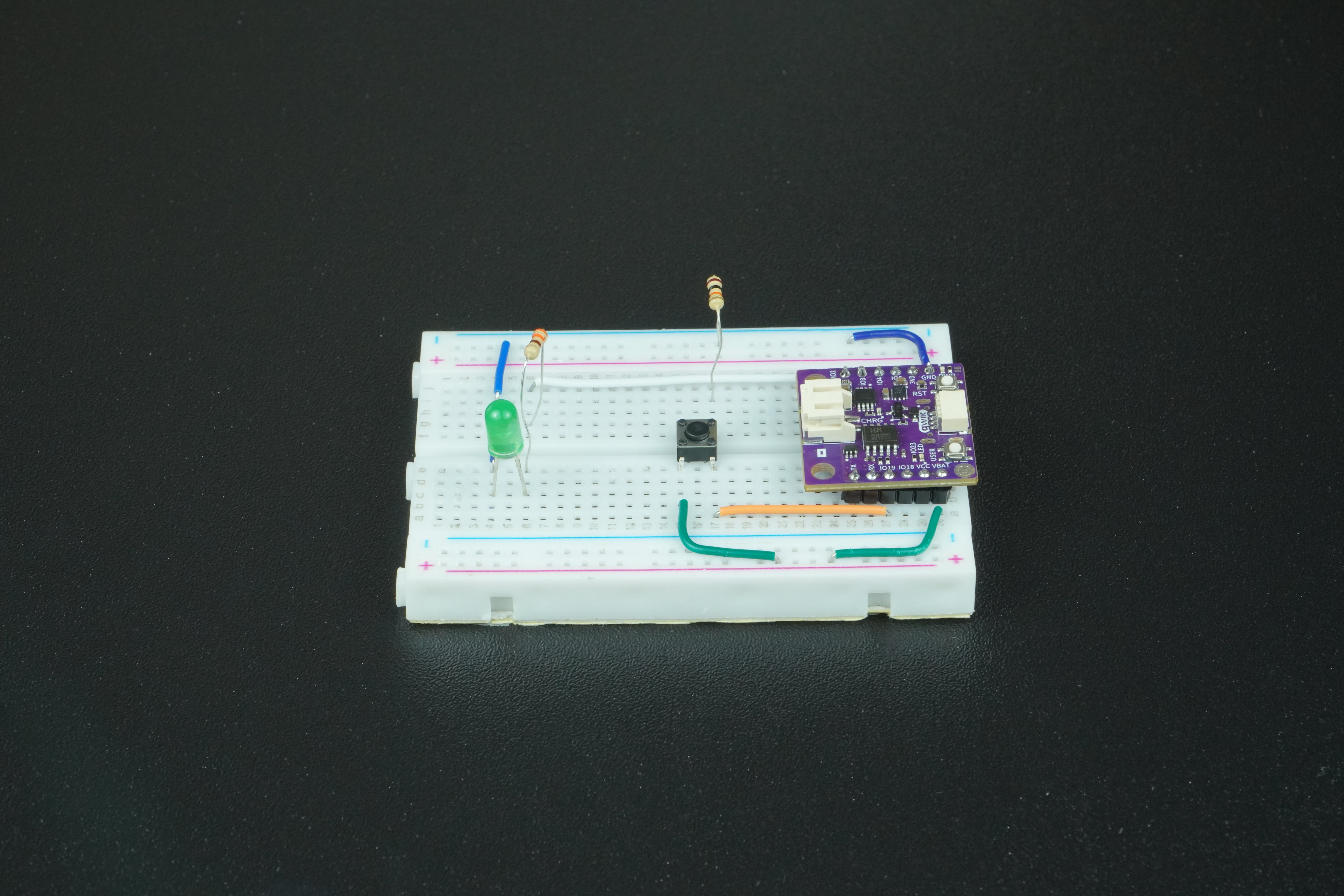
3. Connect the LED to the NULA MINI board
Connect IO4 on the NULA MINI to one leg of a 330Ω resistor on the breadboard. Attach the LED’s anode (long leg) to the other side of the resistor, and connect the cathode (short leg) directly to GND on the board. Your completed circuit should look like this:
Reading the button state
To read the button state, we call digitalRead() function. Keep in mind that the pin needs to be set as an INPUT in order to use this function.
The function digitalRead(pin) reads the value from a specified digital pin and returns either HIGH or LOW as result. We call this function inside the loop():
void loop() {

  //digitalRead() is a function that reads the value from a specified digital pin, either HIGH or LOW.
  bool reading = digitalRead(BUTTON_PIN);
}
Button debouncing
When you press a button, it changes from an open circuit to a closed circuit, which we treat as a single press. For us, it feels like one clean action because we react slowly compared to electronics. But to a microcontroller, which checks the button state thousands of times in that short moment, it looks very different.
As the button is pushed, two metal contacts inside touch each other. Since they’re not perfectly smooth or aligned, they can quickly connect and disconnect a few times before settling. To the microcontroller, that looks like the button was pressed several times in a row, even though you only pressed it once.
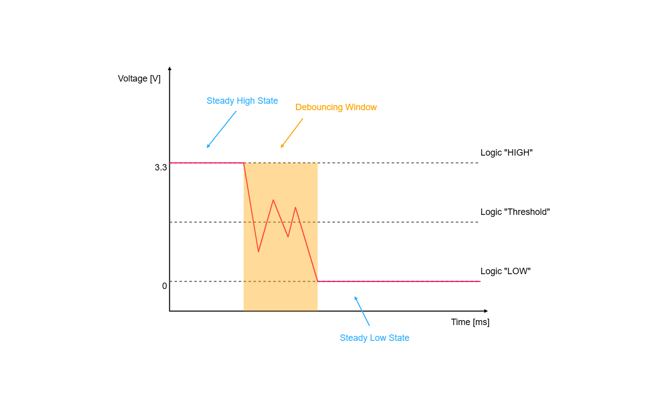
The simplest software-based strategy to handle this is the delay-based debouncer.
The whole point of it is to wait out the debouncing window. This is where the millis() comes in handy.
The function millis() returns the nuber of miliseconds passed since the board began running the current program. We can use it to check if enough time has passed between last button state change and current time, if it has, we are prepared for the next press, if not, wait a bit more.
Toggling the LED
Each time a valid press is detected, we flip the LED's state with a simple toggle. This code is located inside the debouncer filter.
if (lastState == LOW && reading == HIGH) {

      //We toggle the ledState
      ledState = !ledState;

      //We turn the LED on or off depending on the current ledState
      if (ledState == true) {
        digitalWrite(LED_PIN, HIGH);
      } else {
        digitalWrite(LED_PIN, LOW);
      }
    }
    lastState = reading;
Code
Below is the full example code for toggling an LED with a debounced button. It uses the millis() function to check if enough time has passed between button state changes.
/*
This is a variable to which we pass the number of pin that we had connected the BUTTON to.
The NULA board has a pin naming logic as follows: IO19, where 19 is the number that we give to the variable.
If you wish to use a different pin, make sure you are using a IO__ marked pin.
*/
const int BUTTON_PIN = 19;

/*
This is a variable to which we pass the number of pin that we had connected the LED to.
The NULA board has a pin naming logic as follows: IO4, where 4 is the number that we give to the variable.
If you wish to use a different pin, make sure you are using a IO__ marked pin.
*/
const int LED_PIN = 4;

/*
Those are the variables used for button debouncing. To learn more about button debouncing, check out our example
documentation at: <link placeholder>
*/
bool ledState = false;
bool lastState = LOW;
unsigned long lastChangeMs = 0;
const unsigned long debounceMs = 25;

void setup() {

  /*
  pinMode() is a function that configures the specified pin to behave either as an input or in this case as an output.
  This simply means that the pin "listens" for the available data when in input mode, and "writes" data when in output mode.
  As our pin needs to detect if the button has been pressed, we will put the pin in INPUT mode.
  */
  pinMode(BUTTON_PIN, INPUT);

  /*
  pinMode() is a function that configures the specified pin to behave either as an input or in this case as an output.
  This simply means that the pin "listens" for available data when in input mode, and "writes" data when in output mode.
  As our pin needs to turn on the LED, we will put the pin in OUTPUT mode.
  */
  pinMode(LED_PIN, OUTPUT);
}

void loop() {

  //digitalRead() is a function that reads the value from a specified digital pin, either HIGH or LOW.
  bool reading = digitalRead(BUTTON_PIN);

  /*
  millis() is a function that returns the number of milliseconds passed since the board began running the current program.
  In this example, we use this function to check out if the debouncing period has finnished. This number will overflow
  (go back to zero), after approximately 50 days.
  */
  unsigned long now = millis();

  /*
  This is our debouncing logic, we check is the button has been pressed and if enough time has passed so that we dont get
  false readings because of the noise in the signal.
  */
  if (reading != lastState && (now - lastChangeMs) > debounceMs) {
    lastChangeMs = now;

    /*
    As we are using the pull-down method for connecting the button, we need to toggle the LED when the button gets pressed,
    in other words, when the button state goes from LOW to HIGH.
    */
    if (lastState == LOW && reading == HIGH) {

      //We toggle the ledState
      ledState = !ledState;

      //We turn the LED on or off depending on the current ledState
      if (ledState == true) {
        digitalWrite(LED_PIN, HIGH);
      } else {
        digitalWrite(LED_PIN, LOW);
      }
    }
    lastState = reading;
  }
}
Full example
Check out the full example code on the link below:
2.1_Button_Toggle_LED.ino
Example that shows how to toggle LED light with a press of a button