1.2. LED Blinking
Upon starting to learn with microcontrollers, one of the first and most fundamental concepts is controlling the state of digital pins. Pins can either be HIGH (on) or LOW (off). As an introduction, this example shows how to control an LED with the Soldered NULA Mini board.
At the end of this example you will learn:
- How to configure a digital pin as an output to control its state
- How to use
timemodule to pause program execution
Parts required:
- Soldered NULA Mini Board
- Breadboard
- 1 x LED (any color)
- 1 x 330 Ohm resistor
- Some jumper wires

Putting the components together
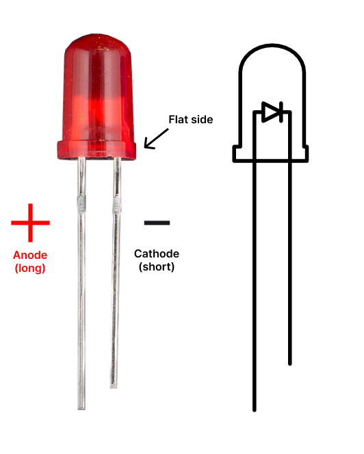
- Before placing the LED on the breadboard, it's important to understand its polarity. LED has two legs: Long leg (anode = positive) and short leg (cathode = negative). Another way to identify the polarity if the legs are the same length
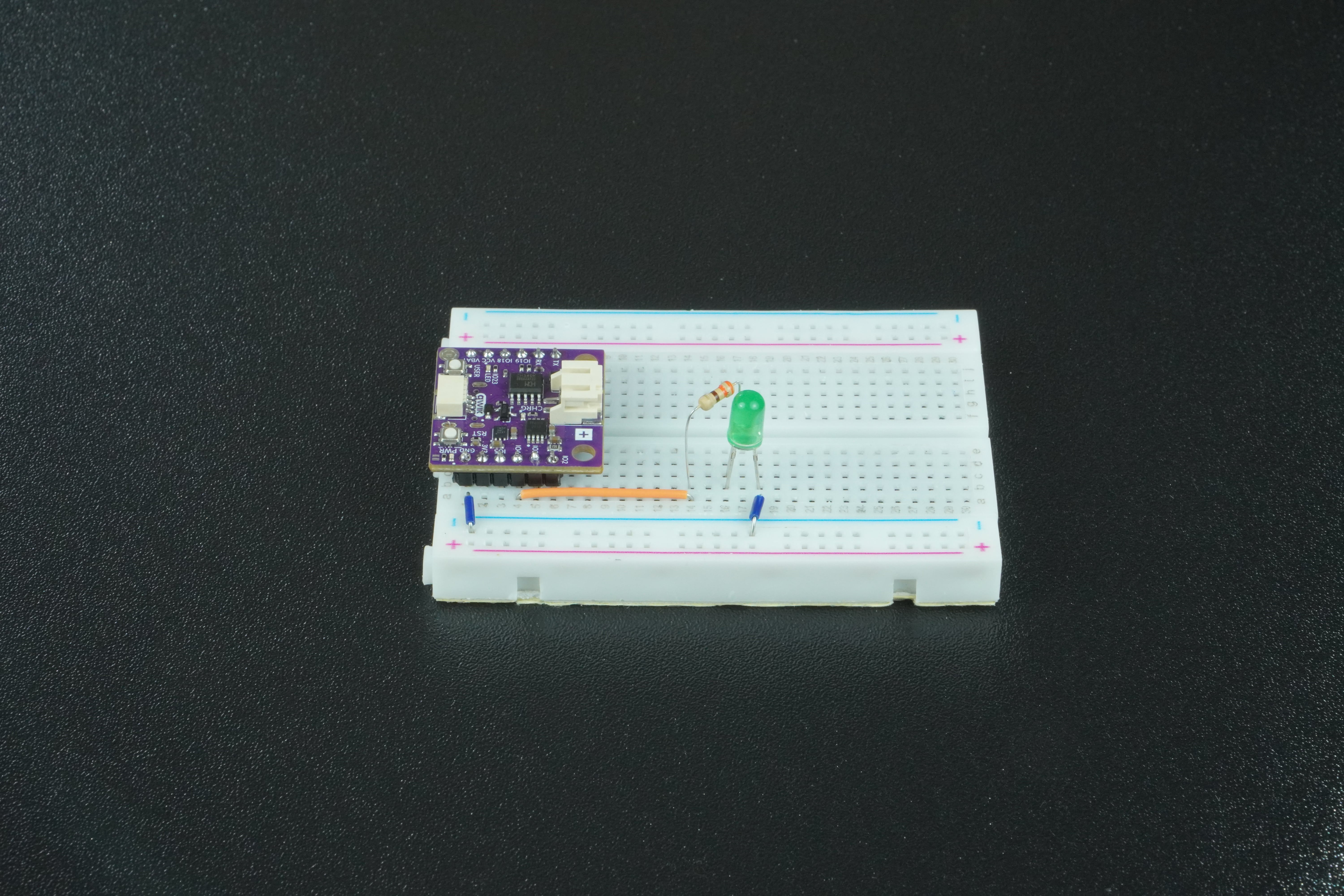
- Place the LED on the breadboard so that each leg is in a different row.
- Connect the long leg of an LED to pin 5 on the board by placing a 330 Ohm resistor between the leg and a jumper wire.
- Connect the short leg of an LED to the GND on the board with a jumper wire.
Code Example
To control the LED, we first need to import Pin from built in machine module to declare the pin for LED, additionaly import time to create delays.
from machine import Pin
import time
Store the pin number on which we connected the LED.
pin_number = 4
Create a Pin object that will be used to control the actual pin on the board by passing in the pin number and specifying the pin to be an output. Second line initialy sets the pins voltage to low (0).
led = Pin(pin_number, Pin.OUT)
led.value(0)
Start infinite loop that alternates between high state and low state on led pin object.
while True:
    led.value(1)		# Turn LED on
    time.sleep(1)		# Pause for 1 sec
    led.value(0)		# Turn LED off
    time.sleep(1)		# Pause for 1 sec