Ch340 – How it works
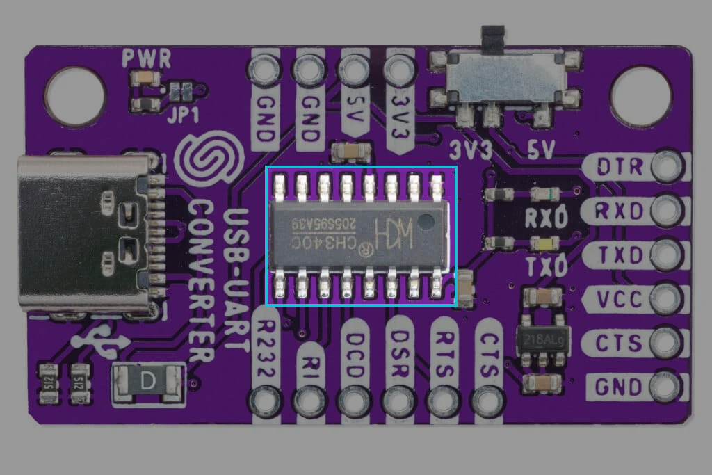
The USB-UART CH340 Converter Board by Soldered enables communication between a computer and a microcontroller or other embedded devices via USB-to-UART conversion. Featuring the CH340G chip, this board supports asynchronous serial communication with baud rates up to 2 Mbps, making it ideal for programming, debugging, and data transfer. It provides 5V and 3.3V compatibility.
Datasheet
For an in-depth look at the technical specifications, refer to the official CH340 Datasheet:
USB to serial chip CH340 Datasheet
Detailed technical documentation for the CH340 converter
How it Works
The CH340G works by converting USB signals into serial communication signals and vice versa. It essentially translates data from the computer’s USB interface into a format that can be understood by microcontrollers, sensors, and other serial devices.
-
USB Data Transfer: The USB interface sends data to the CH340G chip, where it is converted into UART signals. These UART signals are then sent to the TXD (Transmit) and RXD (Receive) pins, enabling data transmission to and from the connected device.
-
Signal Conversion: The CH340G handles the conversion between the USB protocol and the UART protocol. The chip automatically detects the baud rate and flow control settings, making it easy to set up and use.
-
Baud Rate Control: The CH340G supports a wide range of baud rates, ensuring flexibility when connecting to various devices. The default baud rate can be adjusted using software settings or tools like the Arduino IDE or other terminal programs.
-
Flow Control: For more advanced serial communication, the CH340G supports hardware flow control pins like CTS, RTS, DTR, DSR, and DCD. These pins help manage the data flow, preventing data loss during communication.
USB Plug-and-Play Functionality
The CH340 Converter Board is designed for plug-and-play operation with minimal setup. It supports various operating systems, including Windows, macOS, and Linux, and is recognized by the system immediately after connection.
When connected to a computer via USB, the board is powered by the USB port, and data can be transmitted seamlessly to the connected serial device.
How to Connect It?
- Connect Power:
- Connect the VCC pin to the 5V power supply (typically from the USB port).
- Connect GND to the ground of both the computer and the connected device.
- Wiring the Signals:
- Connect TXD from the CH340 to the RXD pin of the target device.
- Connect RXD from the CH340 to the TXD pin of the target device.
- For flow control, connect the corresponding CTS, RTS, DTR, DSR, DCD pins between devices as needed.
- Verify Connections:
- Ensure the TXD and RXD are properly connected for data transfer.
- Confirm that the GND pin is common across both devices.