DRV8424P - Hardware details
Pinout
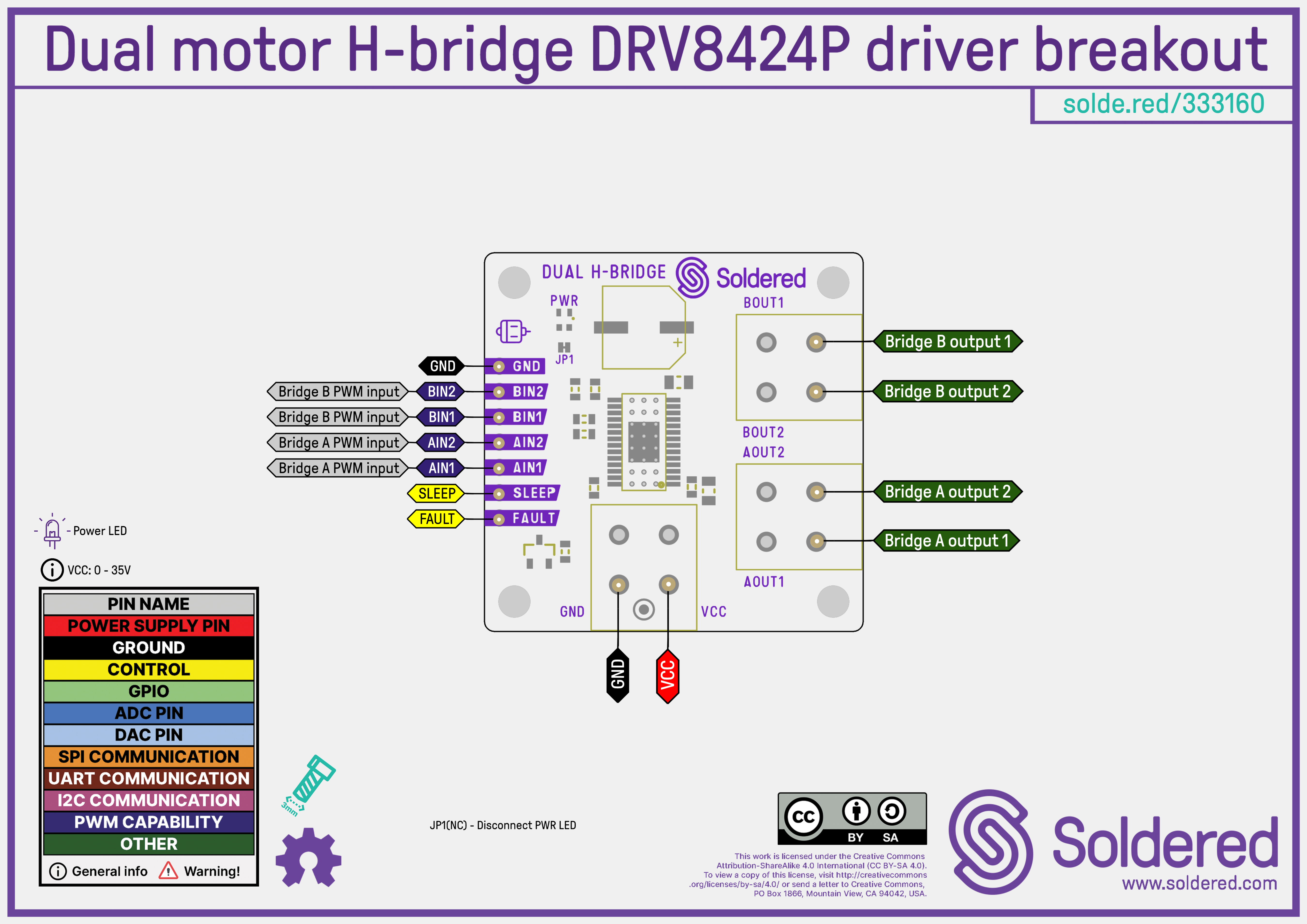
Pin Details
| Pin Marking | Pin Name | Description |
|---|---|---|
| GND | Power/Ground | Common ground for both logic and motor supply. |
| VCC | Power Input | Motor voltage supply input (4.5V to 33V). |
| AIN1 | Logic Input | H-bridge A control input 1 – controls motor A direction. |
| AIN2 | Logic Input | H-bridge A control input 2 – controls motor A direction. |
| BIN1 | Logic Input | H-bridge B control input 1 – controls motor B direction. |
| BIN2 | Logic Input | H-bridge B control input 2 – controls motor B direction. |
| SLEEP | Logic Input | Active-low input. Pull low to enter low-power sleep mode. |
| FAULT | Logic Output | Open-drain output. Goes low during a fault (e.g., overcurrent, thermal). |
| Bridge A Output 1 | Motor Output | Output terminal 1 of H-bridge A (Motor A). |
| Bridge A Output 2 | Motor Output | Output terminal 2 of H-bridge A (Motor A). |
| Bridge B Output 1 | Motor Output | Output terminal 1 of H-bridge B (Motor B). |
| Bridge B Output 2 | Motor Output | Output terminal 2 of H-bridge B (Motor B). |
Dimensions
- Board dimensions: 28 × 22 mm (1.1 × 0.9 inch)
- Pin hole diameter: 1.5 mm
- Mounting holes: M3 (3.2 mm diameter)
- Compatible with LEGO system 🧱
Jumper Details
This board contains one solder jumper:
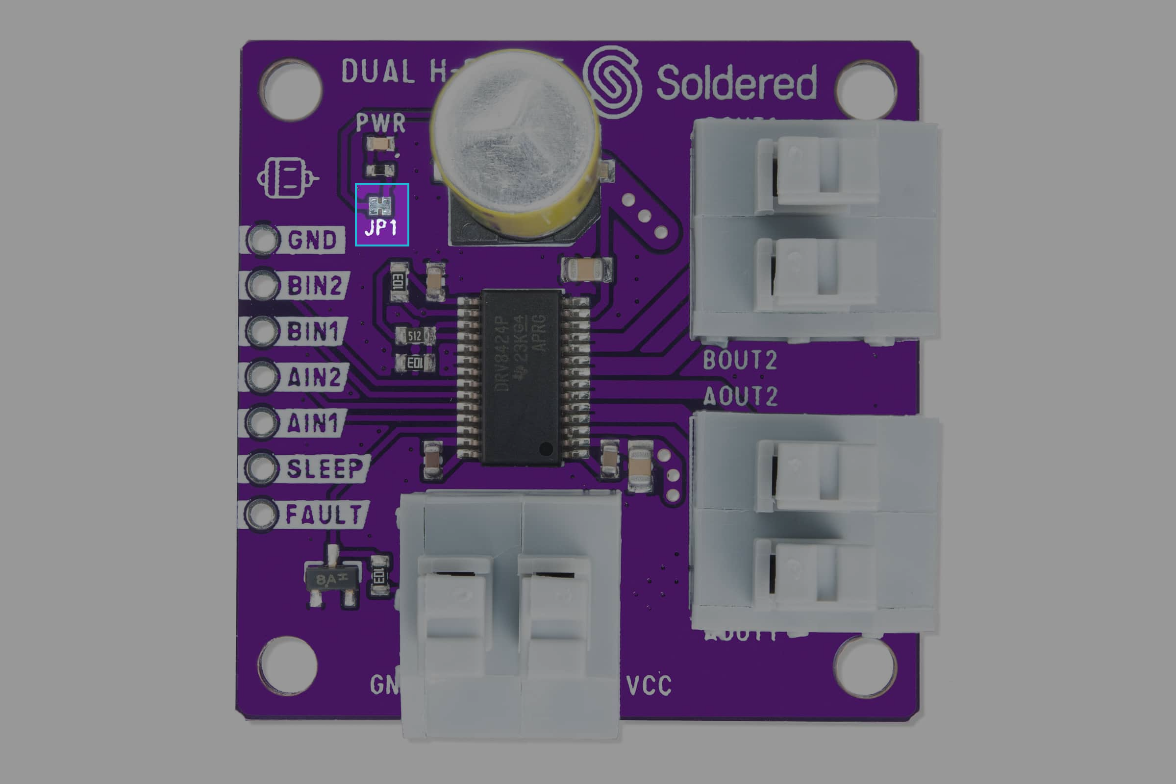
JP1
| Jumper | Default State | Function |
|---|---|---|
| JP1 | NC (closed) | Connects the power indicator LED. |
Hardware repository
Schematics, KiCad project files, Gerber outputs, and more are available in the GitHub repository:
DRV8424P Dual Motor Driver Hardware Repository
Hardware design files for the dual motor H-bridge DRV8424P driver breakout board.
Available files
CAD Files
The project is designed using KiCad, an open-source PCB suite. The .kicad_pro file contains the full schematic and board layout.
Schematic
The schematic diagram in .pdf format can be found in the OUTPUTS folder.
BOM (Bill of Materials)
- A
.csvfile listing all components, quantities, and part numbers. - An interactive BOM (
.html) with visual identification of components on the board.
3D Model
A .step file of the PCB is provided for use in CAD and mechanical modeling applications.
Gerber Files
Used for manufacturing, the Gerber files include:
- Copper layers (
.Cu.gbr) - Solder mask layers (
.Mask.gbr) - Silkscreen layers (
.Silkscreen.gbr) - Paste layers (
.Paste.gbr) - Drill files (
.drl) - Board outline (
.Edge_Cuts.gbr) - Gerber job file (
.gbrjob)
Compliance
Includes necessary documentation to certify safety and legal compliance:
- CE
- UKCA
- Safety Instructions (EN & DE)
- Info.txt – includes SKU, HS code, and manufacturing details