Lcd I2C – How it works
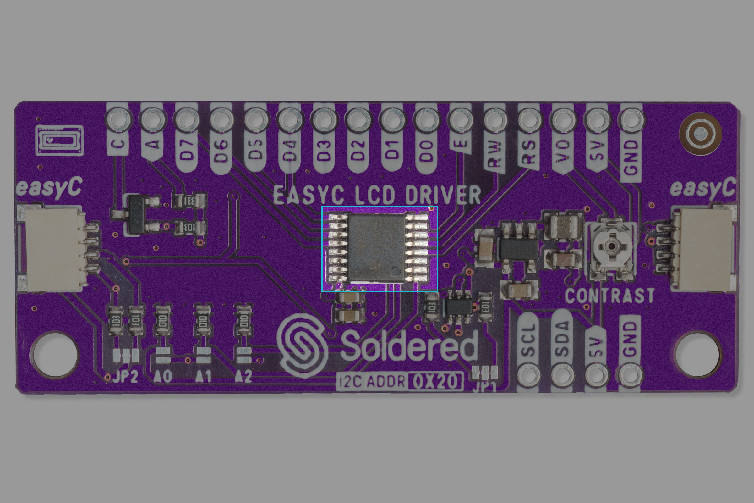
The LCD I2C displays utilize an I/O expander TCA9534 made by Texas Instruments.
Datasheet
For an in-depth look at technical specifications, refer to the official TCA9534 Datasheet:
TCA9534 Datasheet
Detailed technical documentation for the TCA9534
How the TCA9534 works
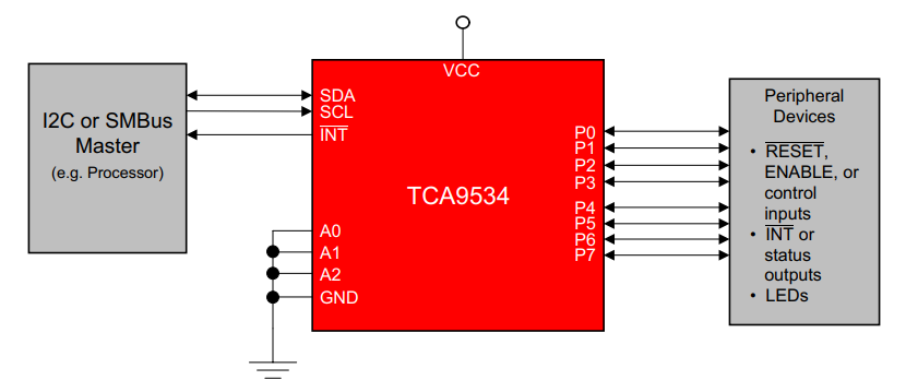
The TCA9534 is a 16-pin device that provides 8-bit general purpose I/O expansion for the I2C bus (or SMBus) protocol.
I/O expanders such as the TCA9534 provide a simple solution when additional I/Os are needed for switches, sensors, push-buttons, LEDs, fans, and other similar devices.
How the LCD Works
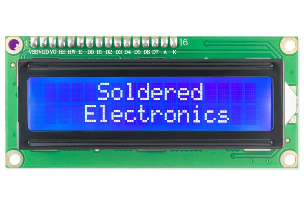
The LCD has a built-in controller that interprets commands and data to display text or symbols. It typically operates in either 4-bit or 8-bit mode, where the microcontroller sends character data and control instructions to manage cursor positioning, display clearing, and text formatting. The LCD refreshes its display based on the received data, making it a versatile component for visual feedback in embedded systems.
Communication Process
This section describes how the TCA9534 I/O expander and the 16x2 LCD I2C display work together.
1. Initialization
Upon powering up, the adapter is set to its default state, where all I/O pins are configured as inputs. The microcontroller initializes the adapter by configuring the necessary pins as outputs for LCD control and data transfer.
2. Sending Commands
The microcontroller communicates with the adapter using I2C commands. The process involves:
-
Start Condition: The leader (microcontroller) sends a start condition to indicate the beginning of communication.
-
Device Addressing: The adapter responds when its assigned address is detected.
-
Command Transmission: The microcontroller sends commands or data, which the adapter translates into parallel signals for the LCD.
-
Acknowledgment: The adapter acknowledges receipt of each byte to confirm successful transmission.
-
Stop Condition: The master sends a stop condition to indicate the end of transmission.
3. Displaying Data
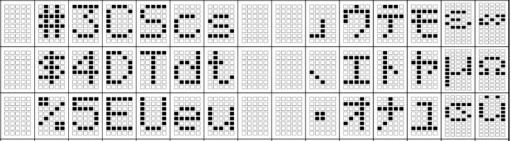
The LCD receives parallel data from the adapter, which updates the display accordingly. Characters, symbols, and special instructions (such as cursor positioning) are managed using standard LCD command sets.
4. Reading Input (If Applicable)
If configured for input operations, the adapter can read button presses or sensor signals and notify the microcontroller via the INT (interrupt) pin.
Other Applications
- Expanding general purpose I/O for microcontrollers
- Reading switches and sensors
- Industrial automation systems
- Smart home and IoT applications