Lo-Fi Noise Machine - Assembly Guide
On this page, we will guide you step by step on how to assemble this kit.
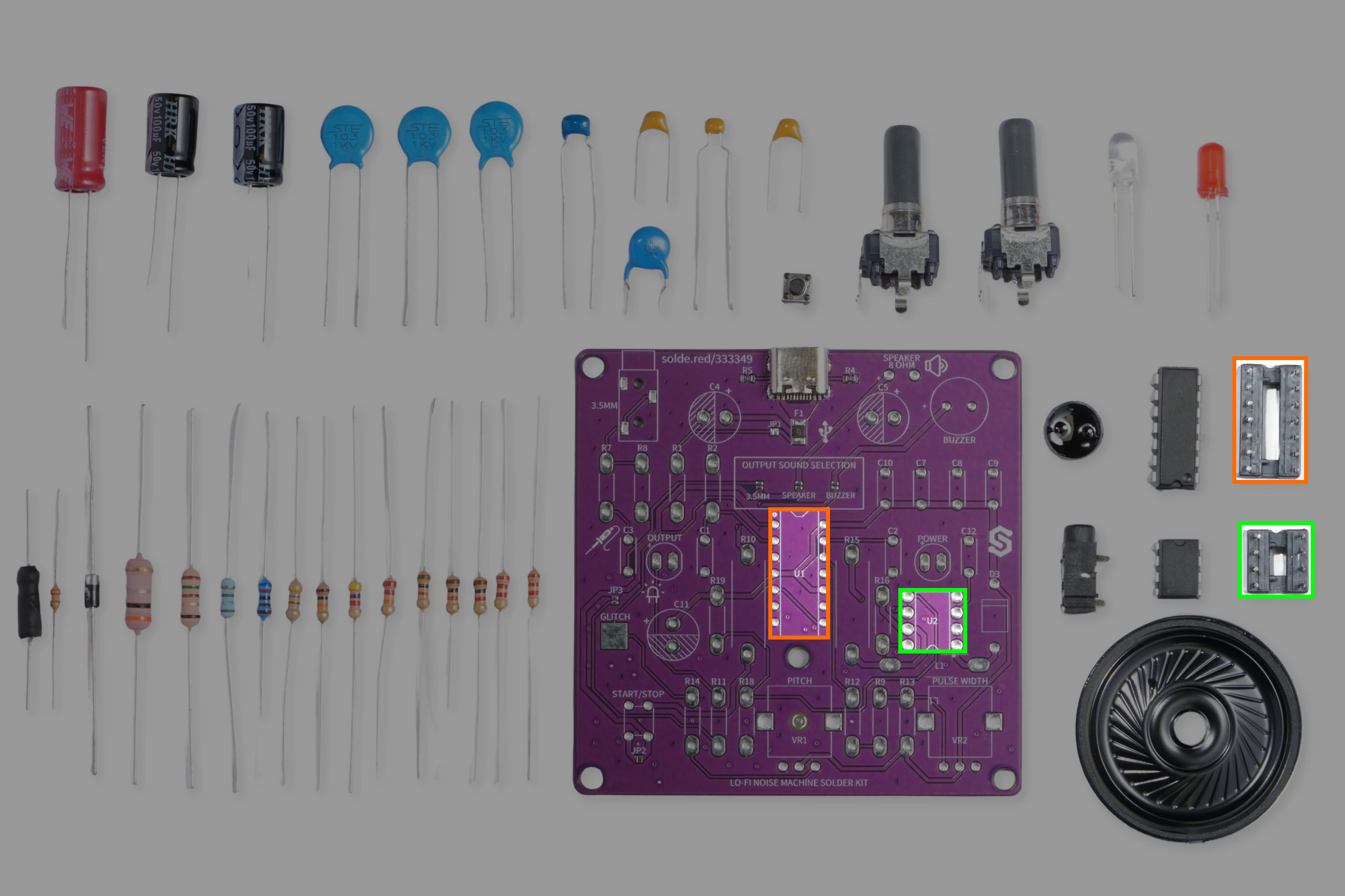
Step 1: Solder the IC sockets
We'll start of by soldering the IC sockets for out NE556 timer and power regulator. Be mindful of their orientation, align the notch from the socket with the notch on the breadboard.
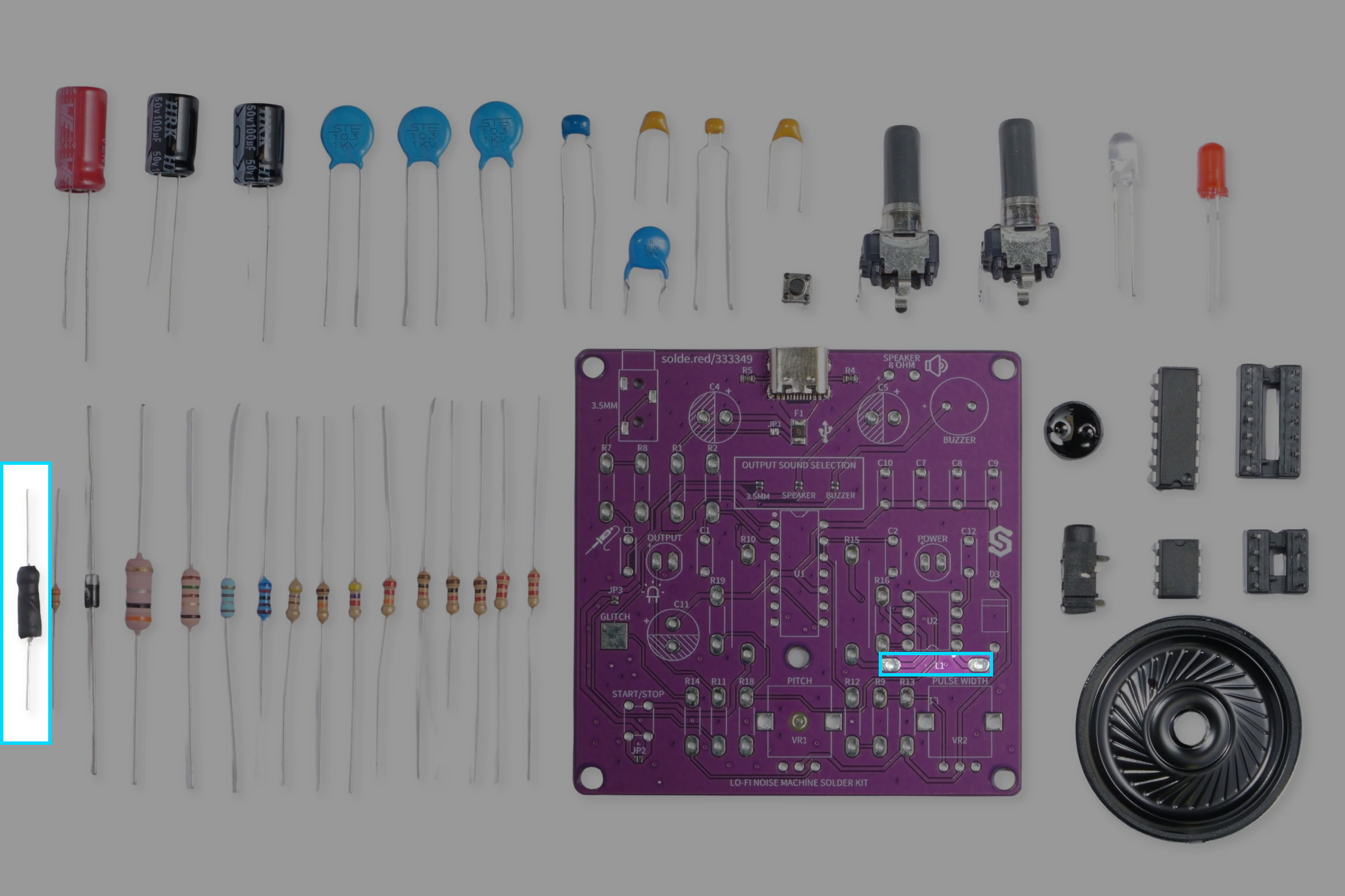
Step 2: Solder the inductor
Because of its placement, we recommend soldering the inductor now as it will be easier while the board is still empty. This component is labeled L1 on the PCB.
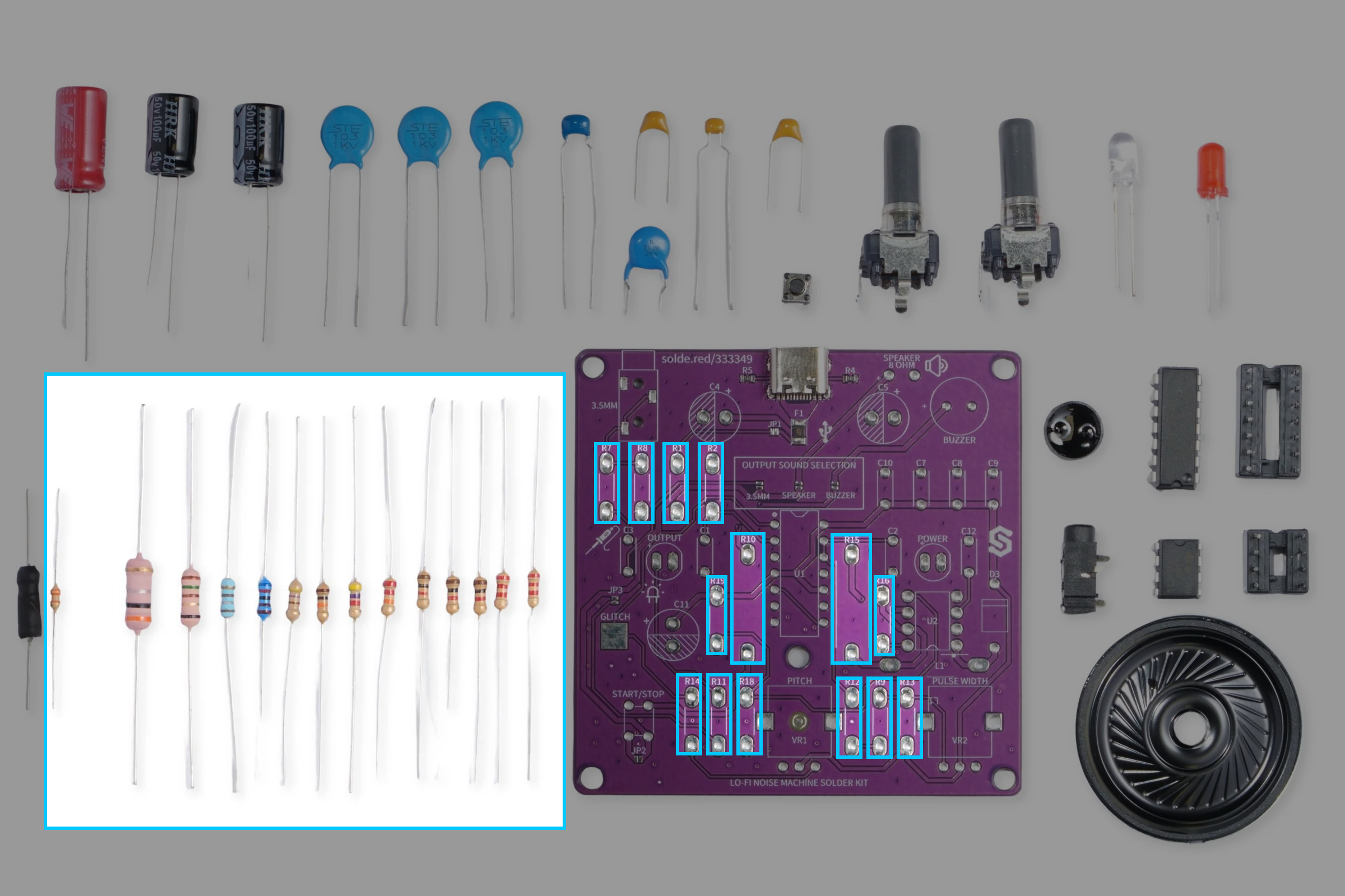
Step 3: Solder the resistors
Next, we'll solder all the resistors to the PCB. We have a total of 14 resistors. Resistors use color codes printed on their bodies to represent their resistance and tolerance value. Take a look at the table below:
| Resistor | Value | Reference image (Color codes) |
|---|---|---|
| R2, R9, R18 | 1 kΩ |  |
| R1, R11 | 2.2 kΩ | 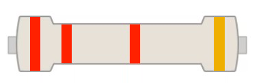 |
| R7 | 10 kΩ |  |
| R8 | 4.7 kΩ |  |
| R10 | 150R 1W | 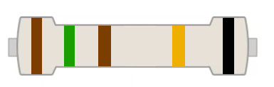 |
| R12 | 470R | 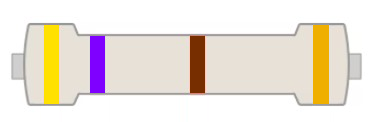 |
| R13 | 22 kΩ |  |
| R14 | 33 kΩ | 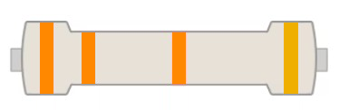 |
| R15 | 0.3R 2W |  |
| R16 | 180R | 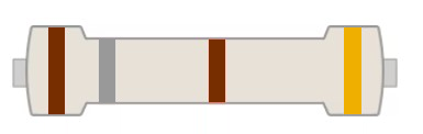 |
| R19 | 6.2 kΩ |  |
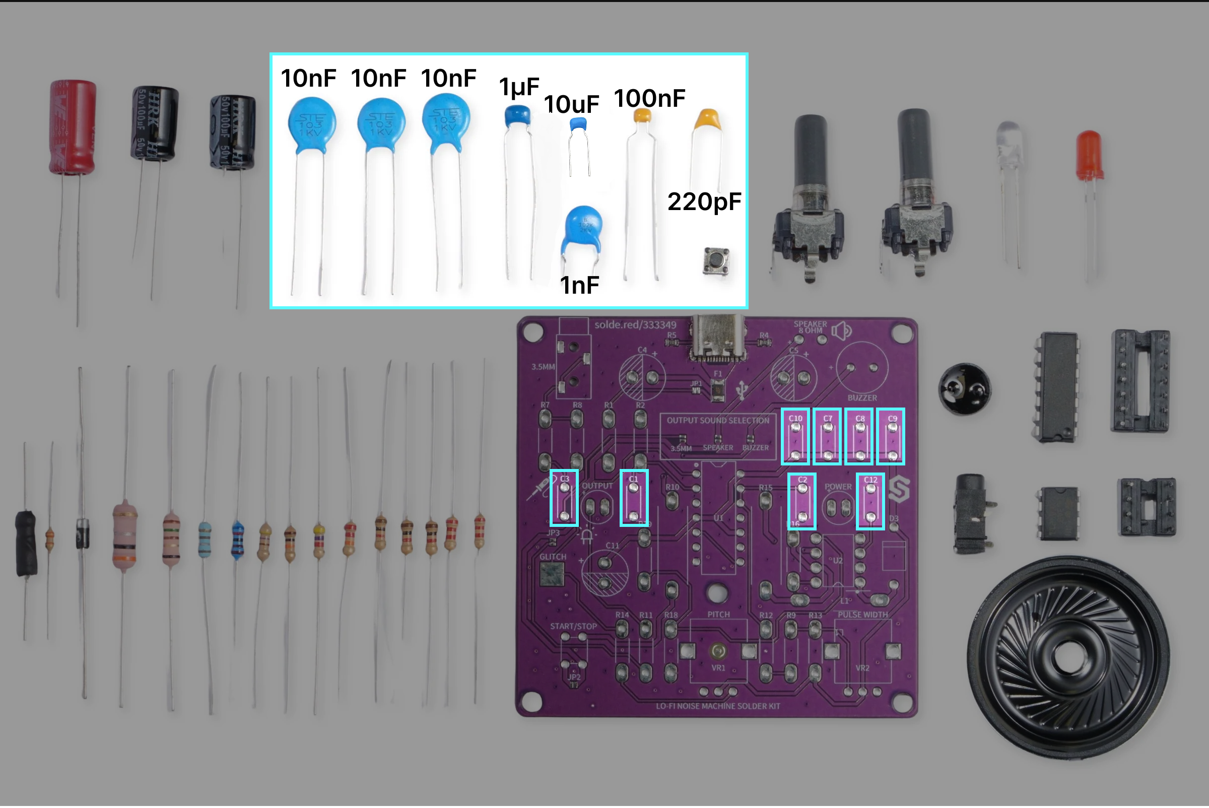
Step 4: Solder the capacitors
Now, let's solder the capacitors. There are a total of 11 capacitors to be soldered, out of which 8 are ceramic capacitors and 3 electrolytic capacitors.

Soldering ceramic capacitors
As mentioned above, these types of capacitors are not polarized, meaning you can rotate them how ever you want. Below is a reference table showing where to solder each ceramic capacitor:
| Capacitor | Value |
|---|---|
| C1, C2, C8 | 10nF |
| C3 | 10uF |
| C7 | 100nF |
| C9 | 1nF |
| C10 | 1uF |
| C12 | 220pF |
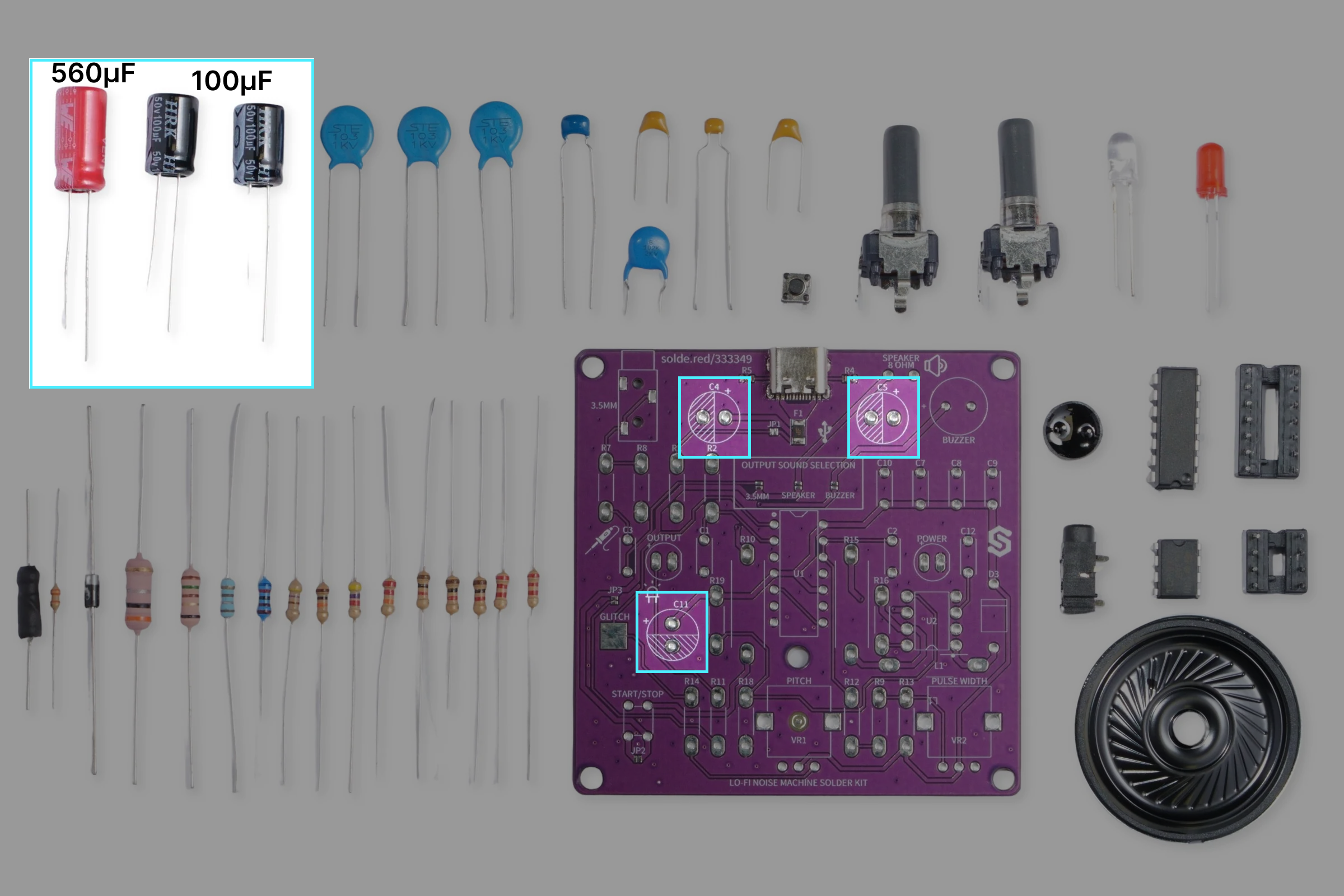
Soldering electrolytic capacitors
Before soldering these capacitors, make sure you check their polarity. The longer leg is positive (+), and shorter leg is negative (-). Additionaly, the negative side is marked with a stripe on the capacitor body, printed with '(-)' symbols. Below is a reference table showing where to solder each electrolytic capacitor:
| Capacitor | Value |
|---|---|
| C4, C11 | 100µF |
| C5 | 560µF |
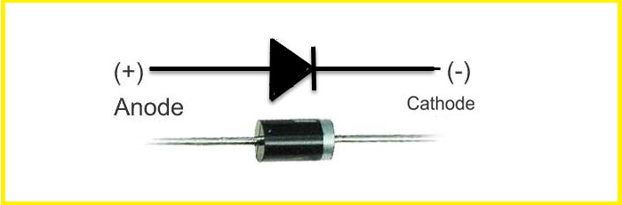
Step 5: Solder the diode
The diode is located at the right side of the PCB, labeled D3. Be mindful of its orientation, take a look at the image below:

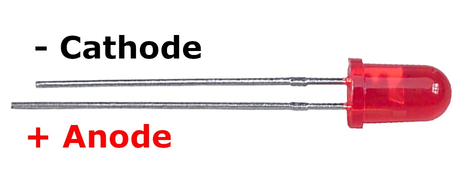
Step 6: Solder the LEDs
When soldering the LEDs, pay attention to which side is positive, and which is negative. The labels for LEDs on the PCB have a positive (left) side marked with a '+' sign.

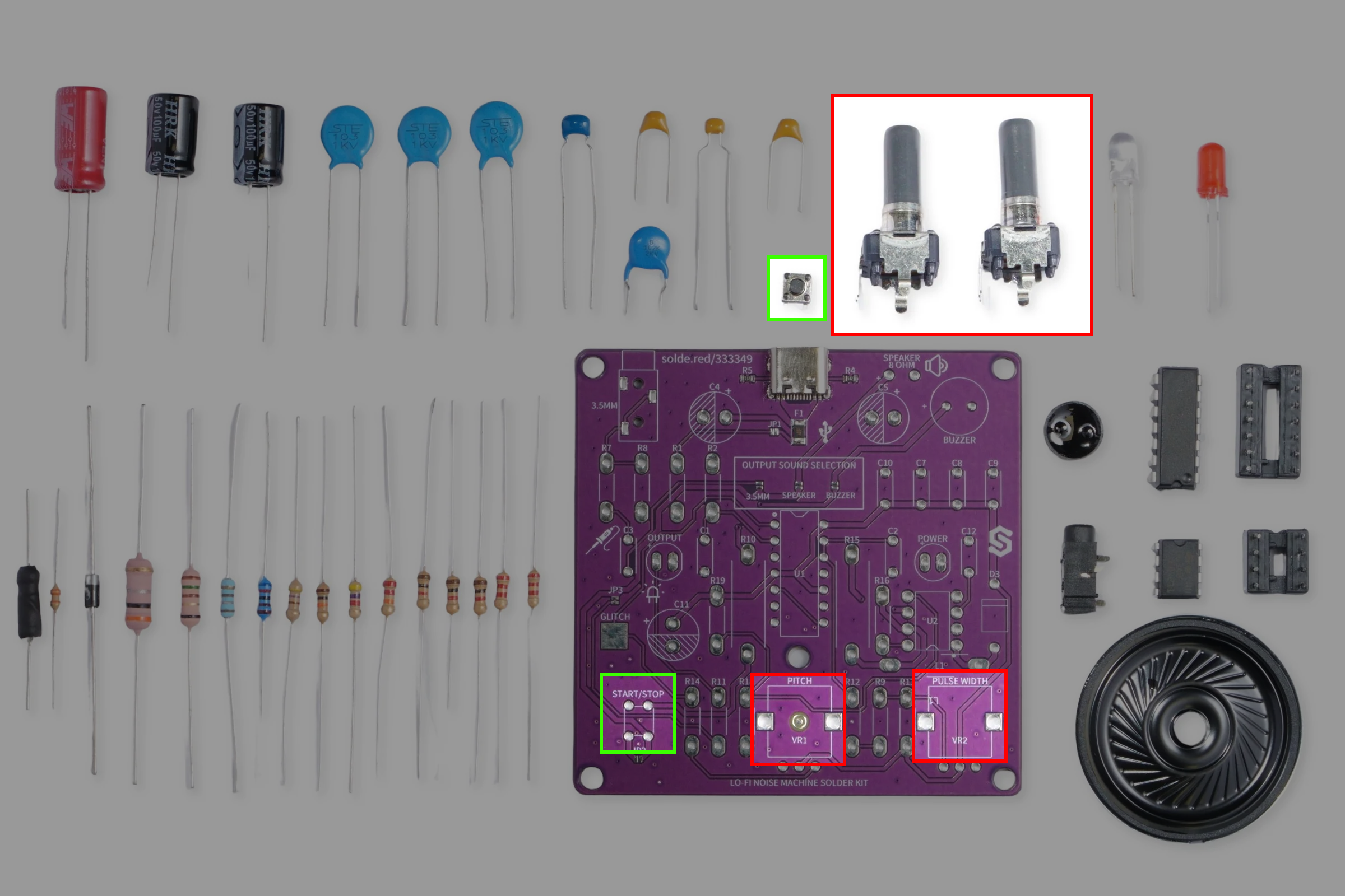
Step 7: Solder the potentiometers and pushbutton
Now, let's solder the mechanical parts.
Potentiometers:
| Label | Value | Function |
|---|---|---|
| VR1 | 500 kΩ | Pitch |
| VR2 | 500 kΩ | Pulse width |
Step 8: Solder audio outputs
And for the final soldering step, attach the 3.5mm audio jack, the buzzer and the speaker wires. Make sure the buzzer and speaker polarity is soldered correctly.

Step 9: Insert the ICs
To finish the build of, insert the two ICs in their sockets which we soldered in the first step. Be careful about their orientation!

All done!
Ready to plug and play!