Macro Pad Solder Kit - Assembly Guide
On this page, we will guide you step by step on how to assemble this kit.
Step 1: Solder the resistors to the PCB.
We'll start by soldering the resistors. In this kit there are 4 different resistor values, which can be identified using their color codes. Each resistor has colored bands that represent its resistance value.
Solder the 10k Ω resistors
You can identify the 10 kΩ reistors by looking at the color code image below, also they come connected in a pack of 8. The places where they need to be soldered on PCB are marked: R5, R6, R10, R18, R19, R20, R21, R22.


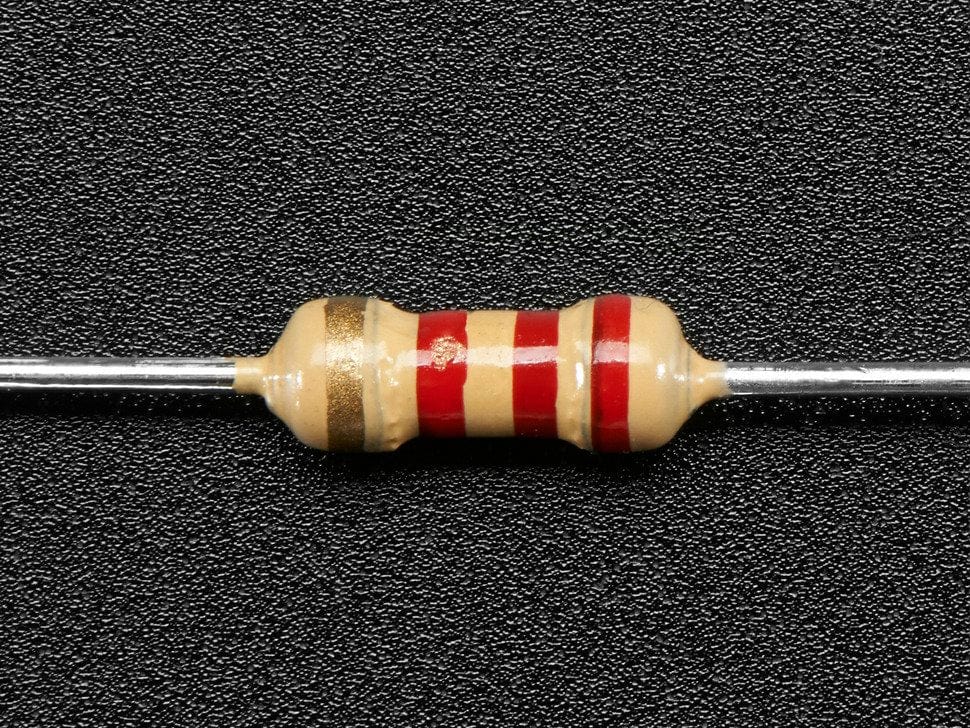
Solder the 470 Ω resistors
The 470 Ω resistors are marked on the PCB by with pins R3, R4.


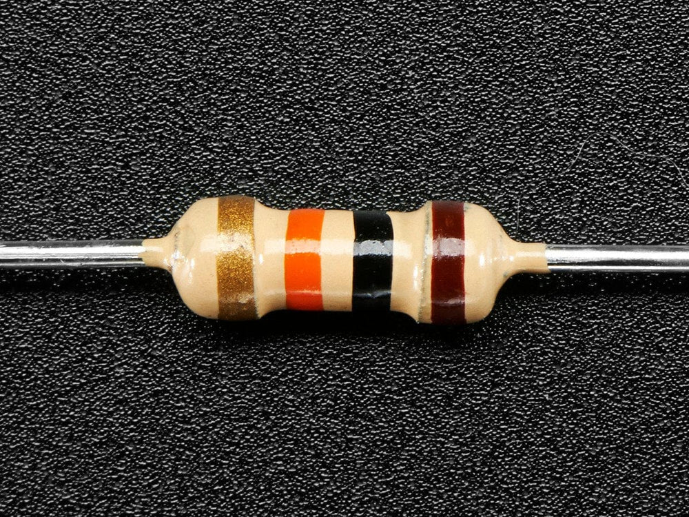
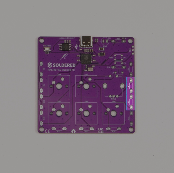
Solder the 1k Ω resistors
Identify the 1k Ω resistors from the image below and solder them to the PCB on pins marked R1, R2.

Solder the 2.2k Ω resistor
The last resistor needs to be soldered on pin marked R16.

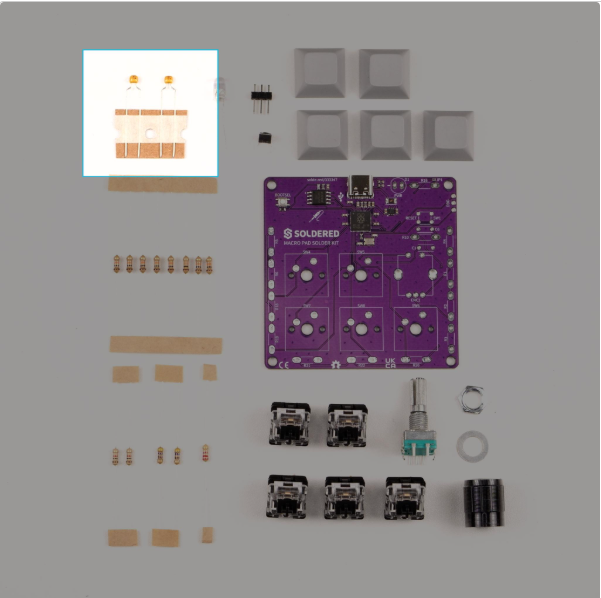
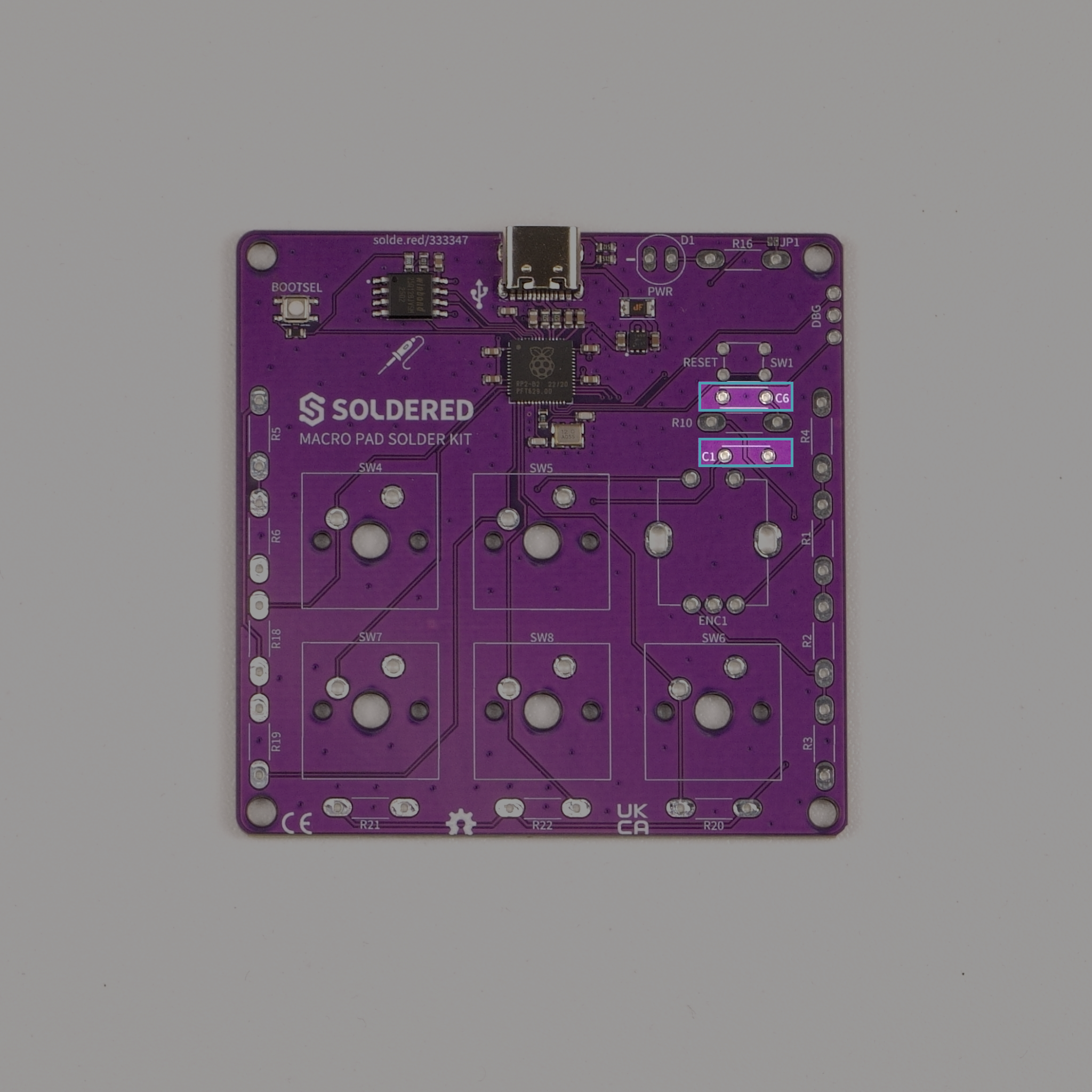
Step 2: Solder the capacitors
This kit includes two 0.1 µF ceramic capacitors. Their placements on the PCB are marked C1 and C6.
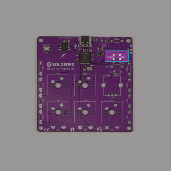
Step 3: Solder the pushbutton
Solder the 4 legs of a pushbutton on pin marked SW1, this will act as our RESET button.
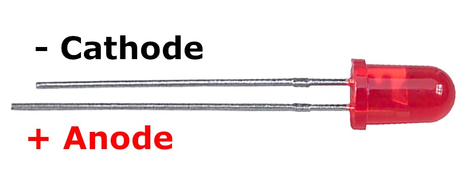
Step 4: Solder the LED
Solder the LED on pin D1. Keep in mind that the LED's cathode (-) is on the left pin, and anode (+) is on the right pin!

Step 5: Solder the switches and rotary encoder
And for the final step, we'll solder the main mechanical components: five MX switches and one rotary encoder.


All done!
Now, simply plug in via USB-C.