CAN Transciever MCP2518 - CANFD Communication example
This page contains a full communication example between two Dasduino COREs using the MCP2518 modules and CANFD protocol.
Sending frames through CAN network using CANFD
To start sending frames through CAN, first initialize the class instance, to check how to to that, visit the page before this one. To send a frame through CAN, call the sendMsgBuf() function. check the example below:
#include "CANBus-SOLDERED.h"
#include <SPI.h>
#define MAX_DATA_SIZE 64
// Change according to your setup
const int SPI_CS_PIN = 10;
// pin for CANBed FD
// const int SPI_CS_PIN = 17;
// const int CAN_INT_PIN = 7;
CANBus CAN(SPI_CS_PIN); // Set CS pin
unsigned char stmp[MAX_DATA_SIZE] = {0}; // Buffer which stores data to send
void setup()
{
Serial.begin(115200); //Begin serial communication with PC
while (0 != CAN.begin(CAN_125K_500K))// Initialize CAN BUS with baud rate of 125 kbps and arbitration rate of 500k
// This should be in while loop because MCP2518
// needs some time to initialize and start function
// properly.
{
Serial.println("CAN init fail, retry..."); // Print information message
delay(100);
}
Serial.println("CAN init ok!");
for (int i = 0; i < MAX_DATA_SIZE; i++) // Fill buffer with ascending numbers
{
stmp[i] = i;
}
}
void loop()
{
CAN.sendMsgBuf(0x01, 0, CANFD::len2dlc(MAX_DATA_SIZE), stmp); // Send data in CAN network
delay(10); // Wait a bit for CAN module to send data
CAN.sendMsgBuf(0x04, 0, CANFD::len2dlc(MAX_DATA_SIZE), stmp); // Send data in CAN network
delay(500); // Wait a bit not to overfill network
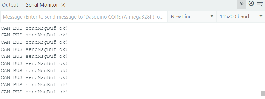
Serial.println("CAN BUS sendMsgBuf ok!"); // Print message
}
Receiving data through CAN network using CAN 2.0
To start receiving data from CAN netwrk, first check if there is data coming by using the checkReceive() function. After that, call the readMsgBuf() function to save received data into a buffer. To check the ID of transmitter call the getCanId() function. Check the example below:
#include "CANBus-SOLDERED.h"
#define MAX_DATA_SIZE 64
// Change according to your setup
const int SPI_CS_PIN = 10;
CANBus CAN(SPI_CS_PIN); // Set CS pin
unsigned char len = 0; // Variable to store length of incoming data
unsigned char buf[MAX_DATA_SIZE]; // Buffer to store incoming data
void setup()
{
Serial.begin(115200); //Begin serial communication with PC
while (0 != CAN.begin(CAN_125K_500K))// Initialize CAN BUS with baud rate of 125 kbps and arbitration rate of 500k
{
Serial.println("CAN init fail, retry..."); // Print information message
delay(100);
}
Serial.println("CAN init ok!");
}
void loop()
{
if (CAN_MSGAVAIL == CAN.checkReceive())
{
CAN.readMsgBuf(&len, buf); // You should call readMsgBuff before getCanId
// This function saves incoming data into buffer buf
// It saves len number of bytes
unsigned long id = CAN.getCanId(); // Get ID of transmitter
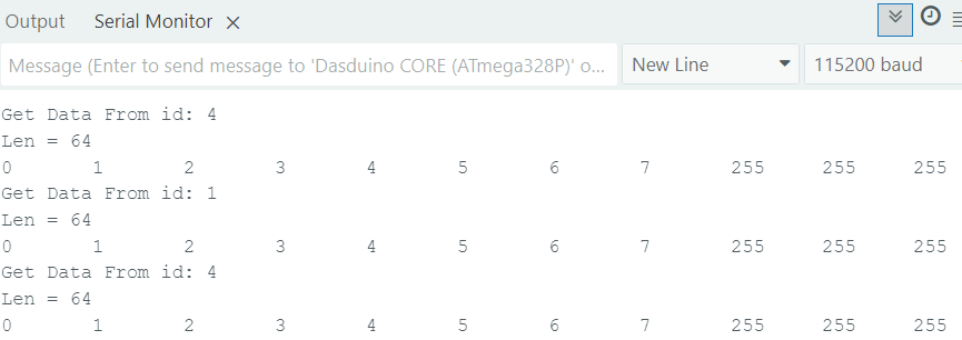
Serial.print("Get Data From id: "); // Print ifnormatio message
Serial.println(id); // Print ID of transmitter
Serial.print("Len = ");
Serial.println(len);// Print length of the data
for (int i = 0; i < len; i++)
{
Serial.print(buf[i]); // Print array with received data
Serial.print("\t"); // Print tabulator to format printing
}
Serial.println(); // Print new line at the end
}
}
After all is connected properlly,you can open two separate Serial monitors on different ports by opening two different sketches. If all the steps were done correctly, Serial monitor output should look like this: