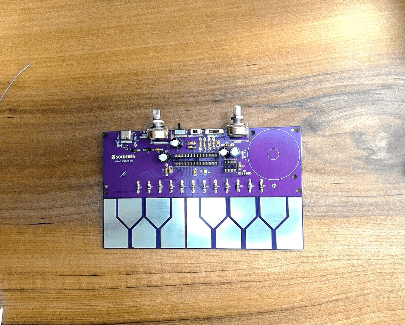
Piano Solder Kit - Assembly Guide
On this page, we'll guide you step-by-step on how to assemble your Piano Solder Kit. Let's go!
Please read the instructions carefully and take all the usual safety precautions when soldering. If you're a beginner, be cautious! You’re holding a 300 °C tool after all — but we know you can do it. 🙂
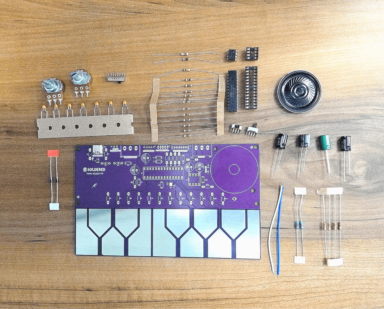
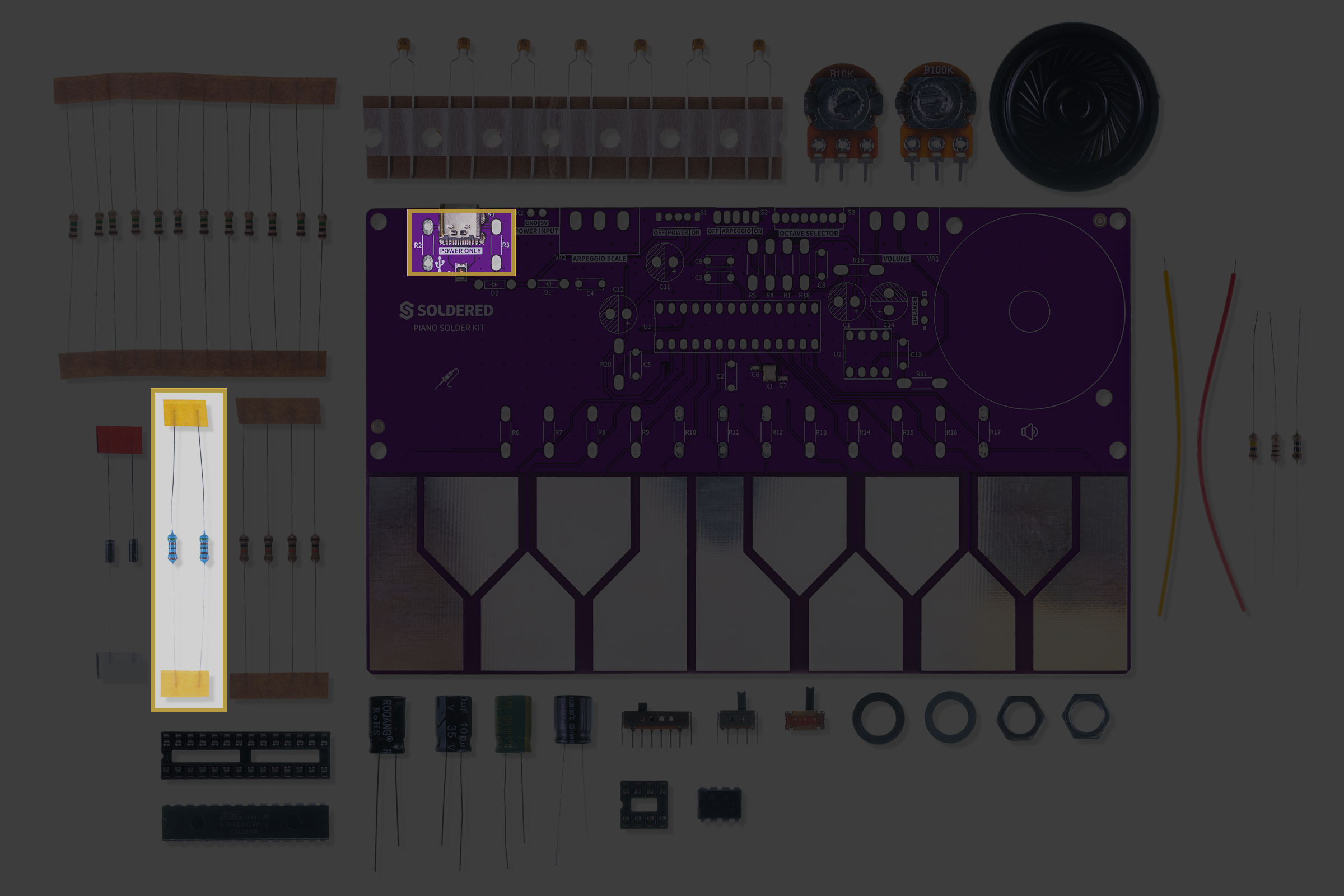
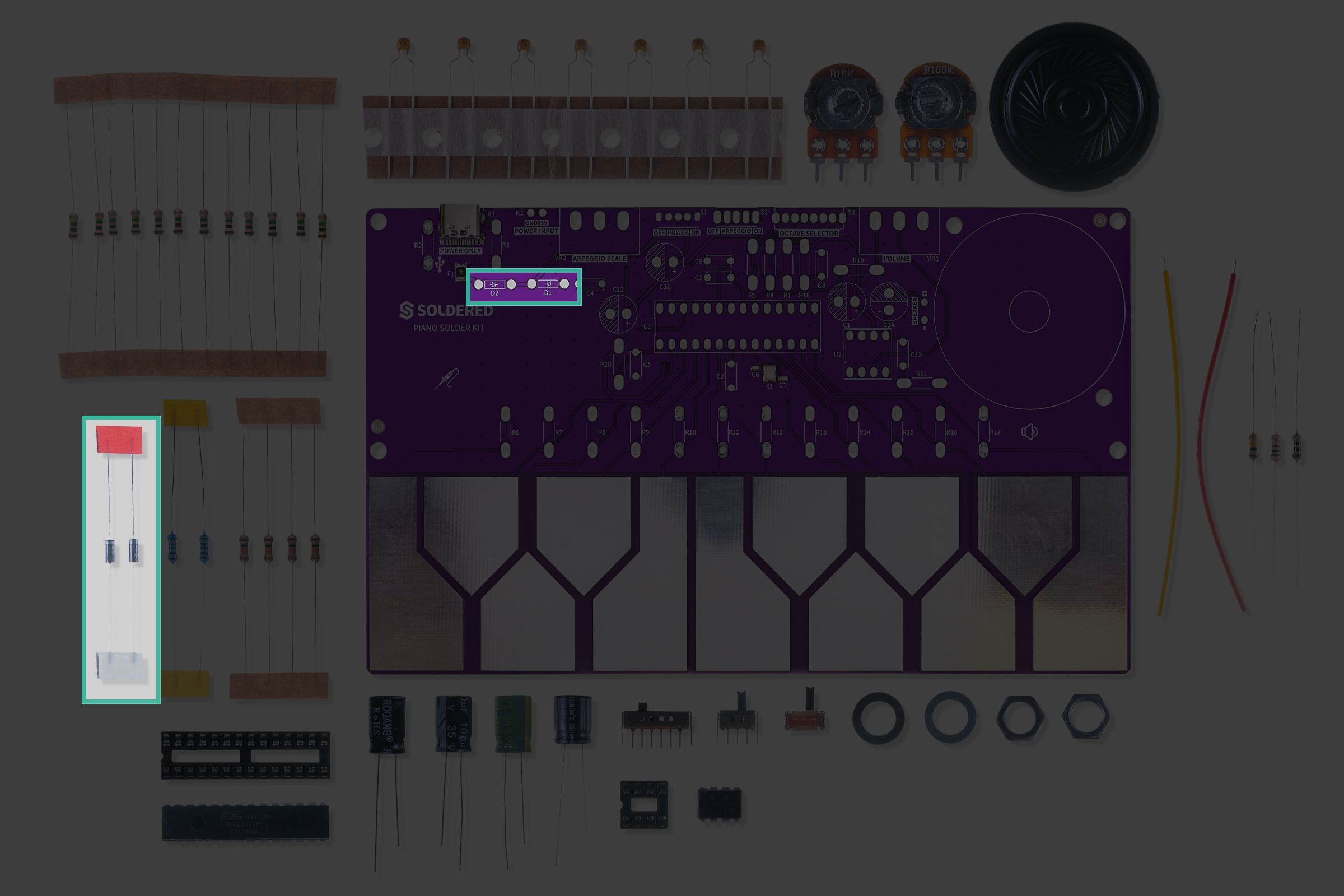
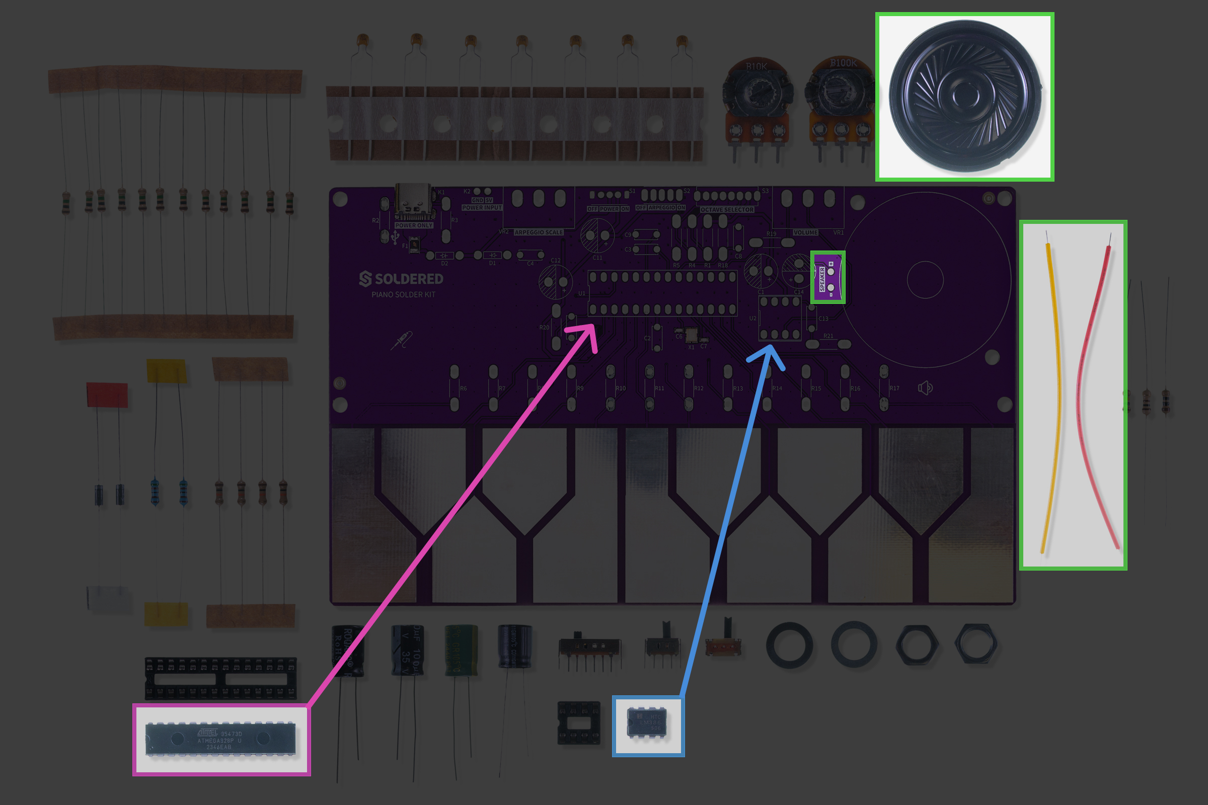
Before starting, make sure you have all the components at hand. You can find the complete components list in the Contents section on the Overview page.
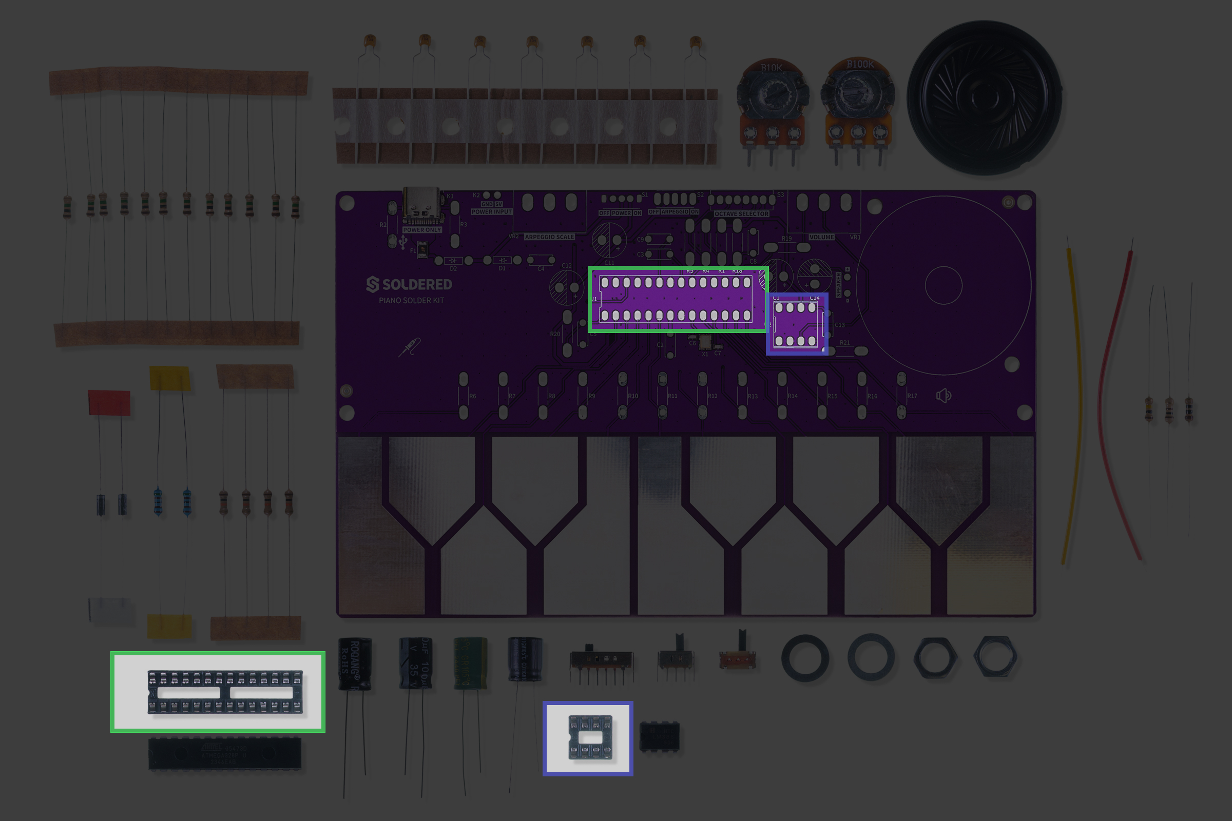
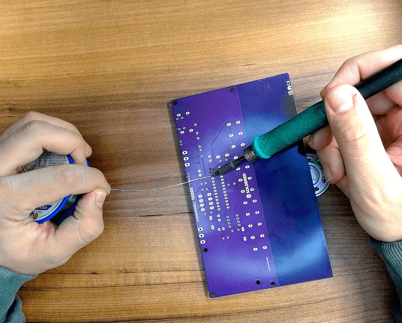
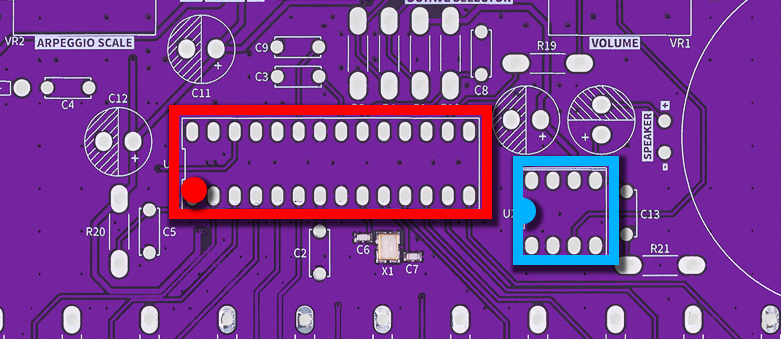
Step 1: Solder the IC sockets
We recommend starting by soldering the IC sockets. Be mindful of their orientation!
Note: Don’t insert the ICs (ATmega328P and LM386) into the sockets until the whole soldering process is complete to avoid damaging them with heat.
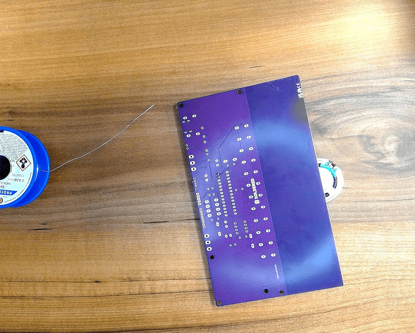
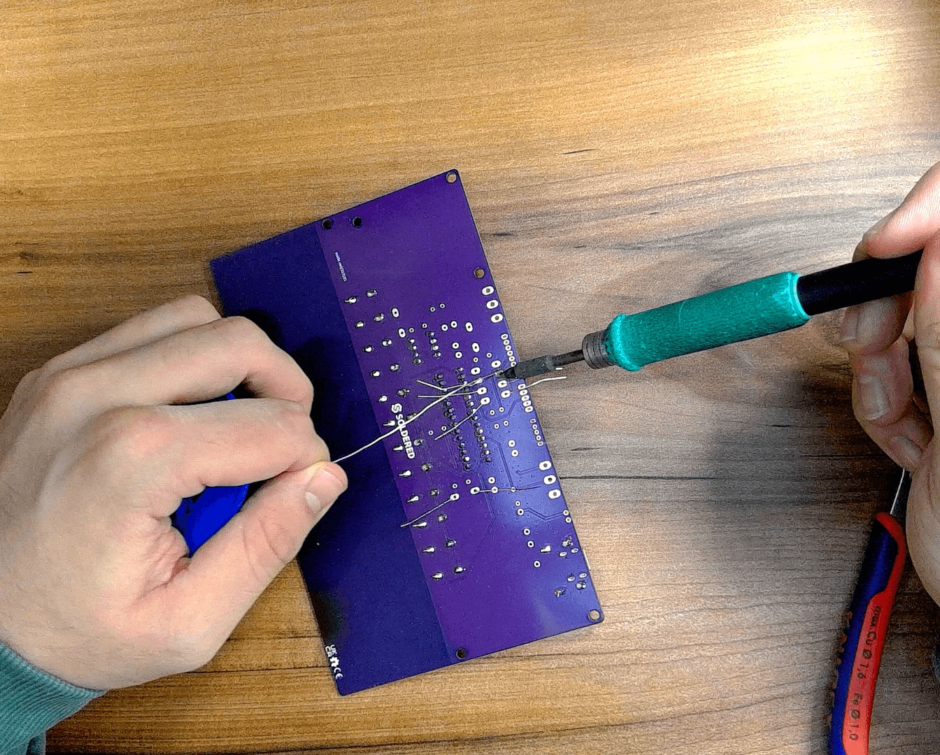
After turning the PCB face down, you can use the included speaker to balance it so it doesn’t rattle:
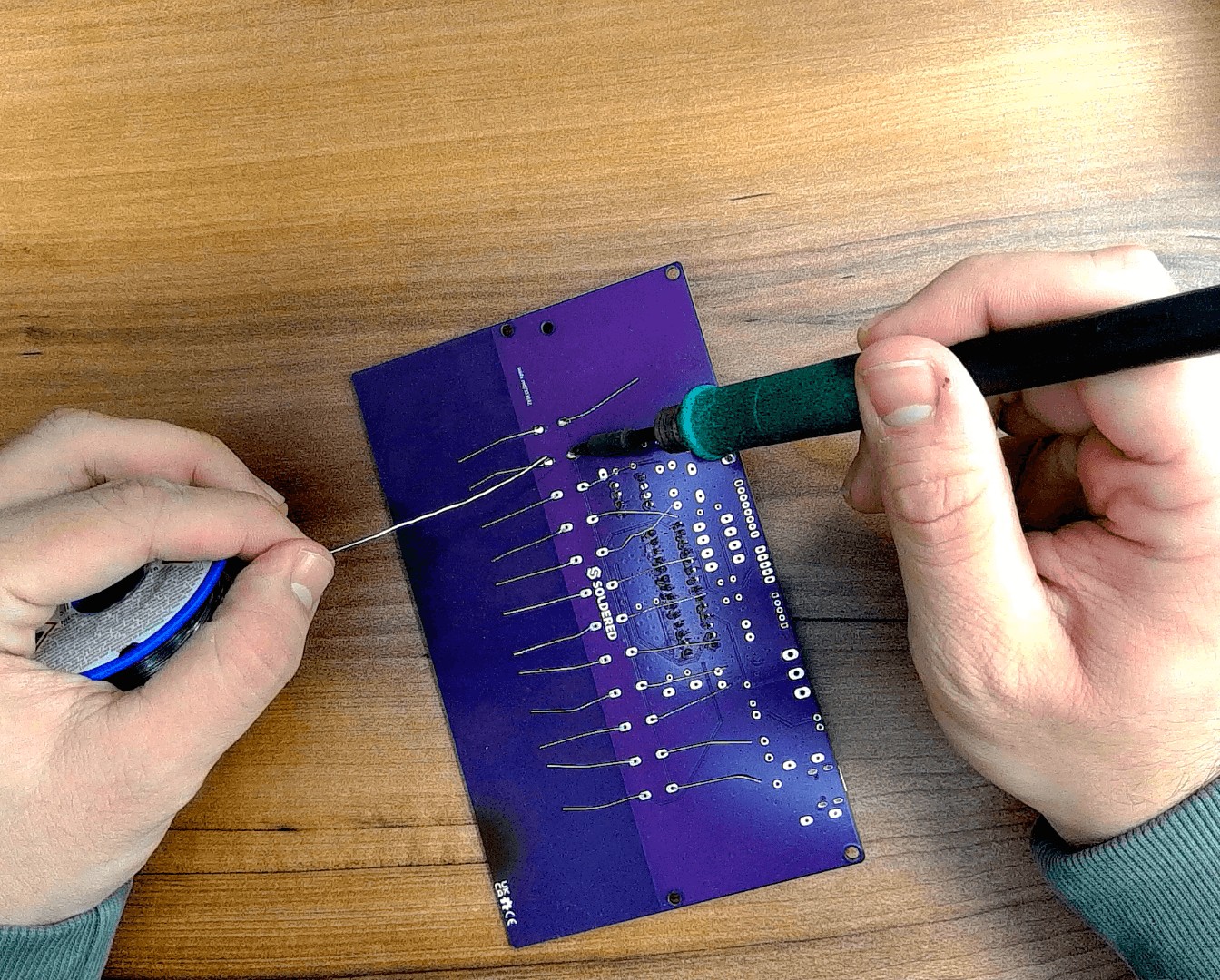
Step 2: Solder the 1 MΩ resistors
Great! Now let’s solder the resistors for the capacitive touch pads.
You can identify the 1 MΩ resistor by this color code:

These will come connected in a pack of 12:
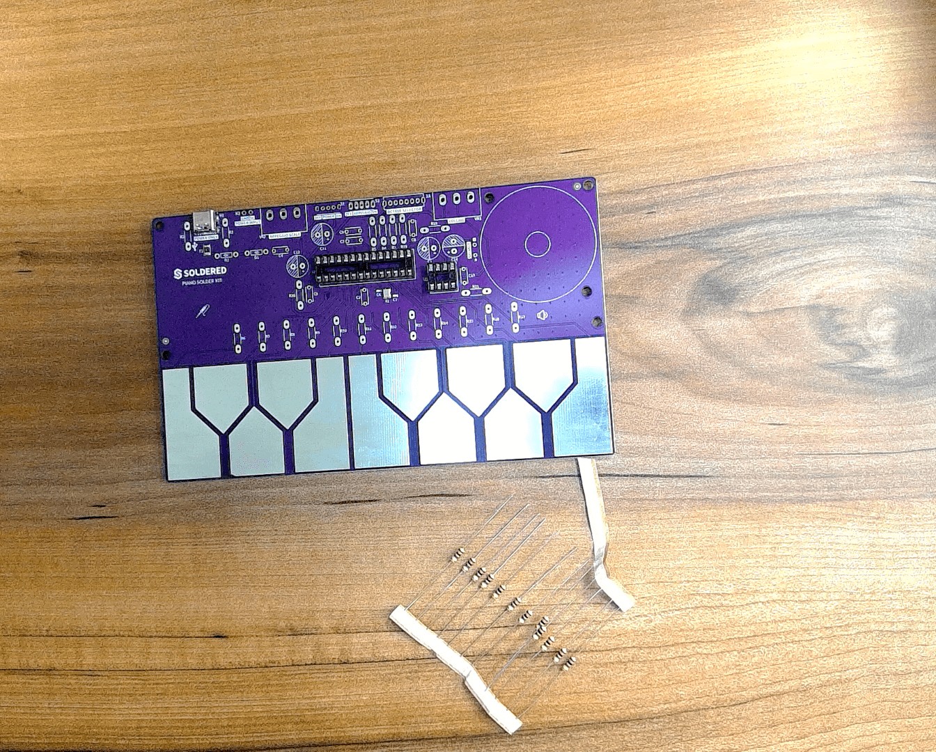
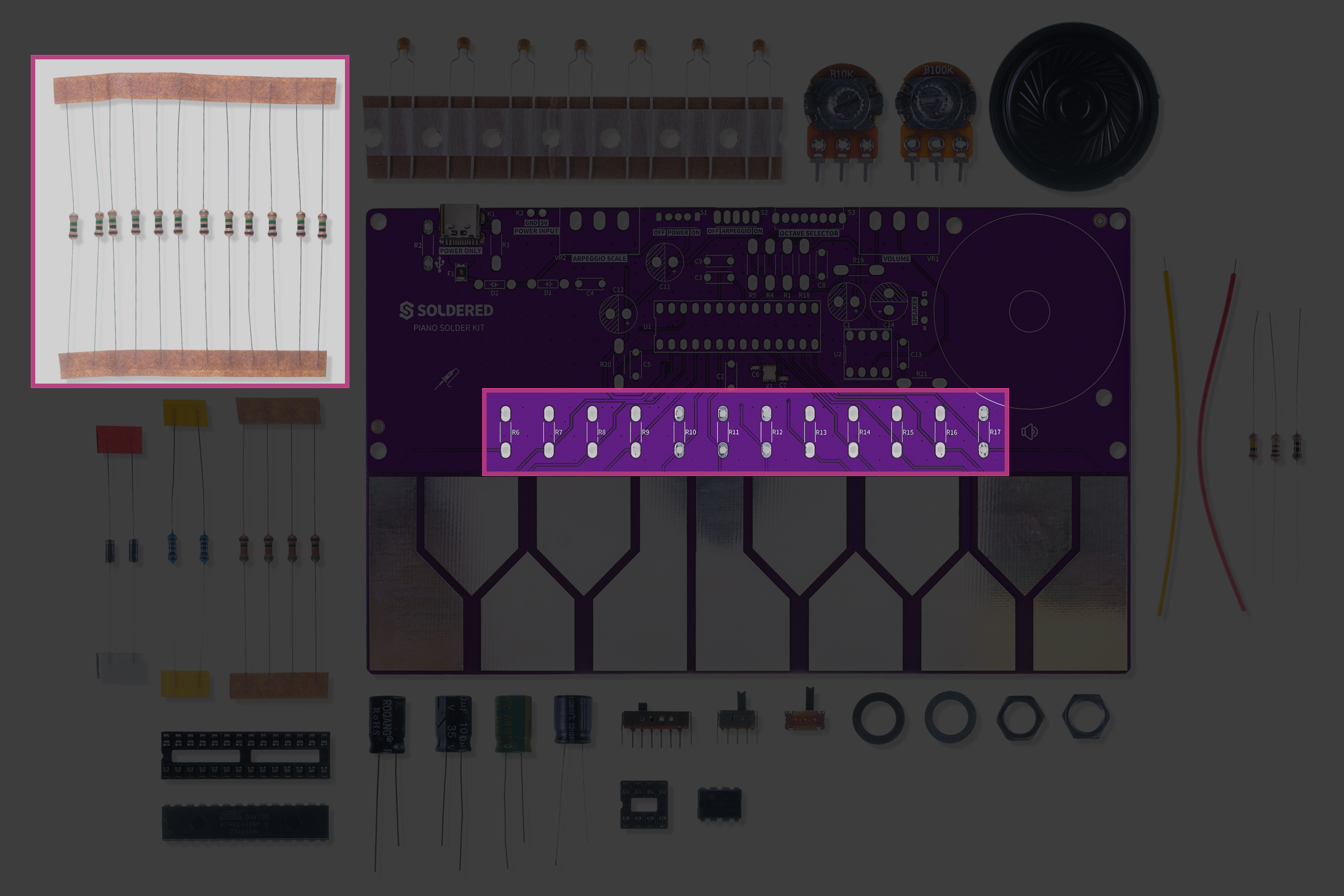
Placement table:
| Resistor | Value | Position on PCB |
|---|---|---|
| R6–R17 | 1 MΩ | Touch pad resistors |
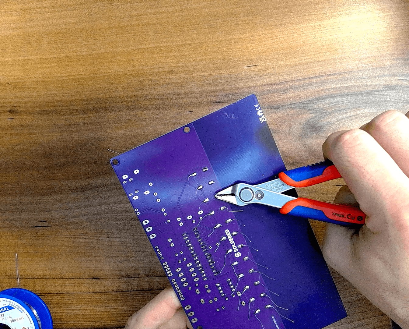
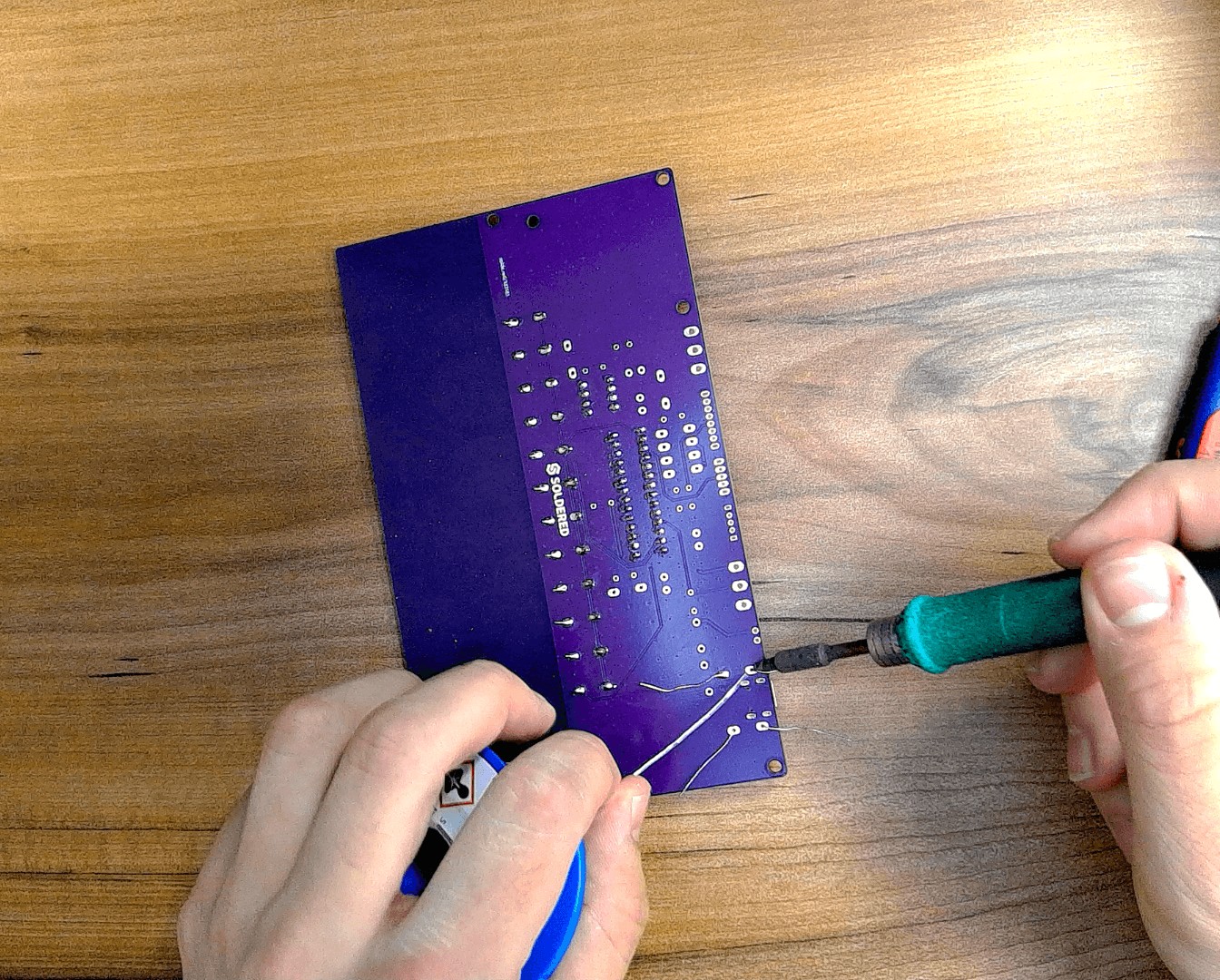
Push each resistor from the front face of the PCB through the two holes and then bend the leads slightly so it stays in place. After placing them all, solder away! You can then snip off the excess leads.
Resistors don’t have polarity — you can place them either way.
This same “bend–insert–bend–solder–cut” procedure applies to all other resistors and similar components, so we won’t describe it again each time.
Step 3: Solder the 5.1 kΩ resistors
You can identify the 5.1 kΩ resistors by their blue (metal film) color — they’re the only blue resistors in the kit.
Placement table:
| Resistor | Value | Position on PCB |
|---|---|---|
| R2, R3 | 5.1 kΩ | Input network resistors |
Step 4: Solder the 10 kΩ resistors
You can identify the 10 kΩ resistor by this color code:

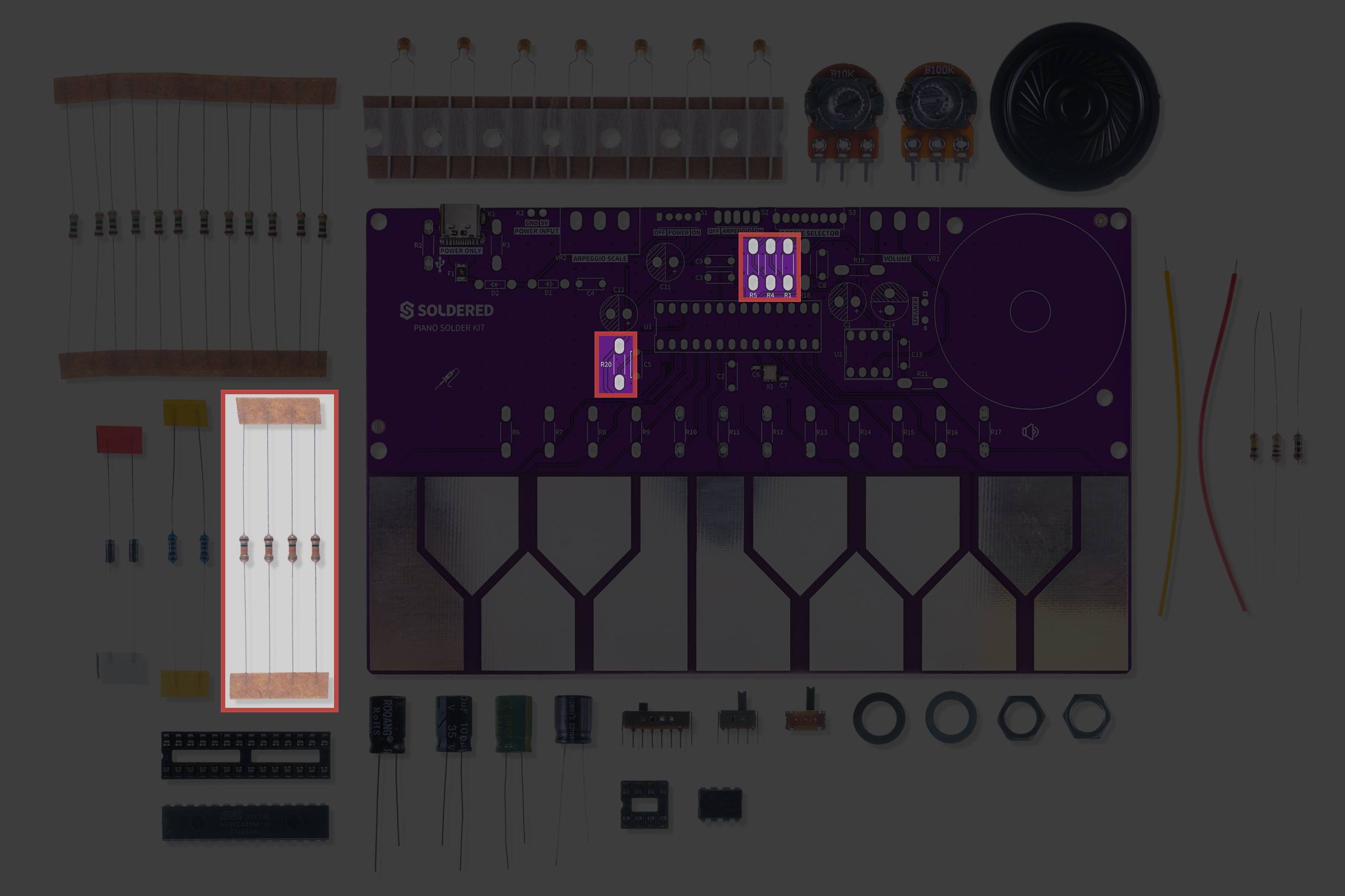
Placement table:
| Resistor | Value | Position on PCB |
|---|---|---|
| R1, R4, R5, R20 | 10 kΩ | Pull-ups and feedback resistors |
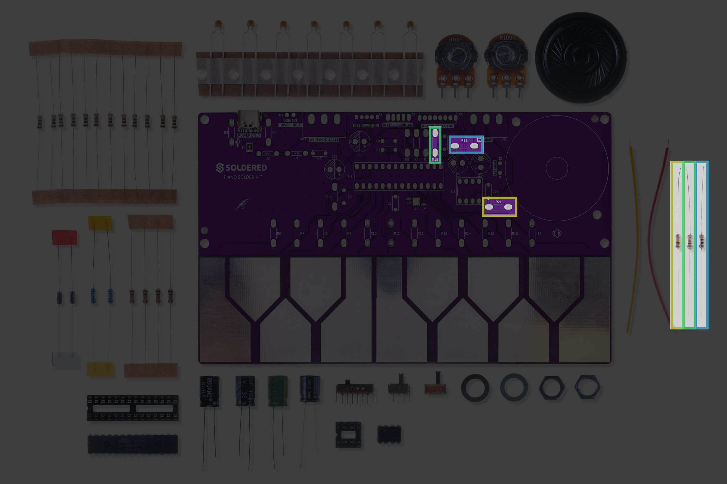
Step 5: Solder the remaining resistors
Let’s solder the remaining three resistors:
| Resistor | Value | Reference Image |
|---|---|---|
| R21 | 10 Ω |  |
| R18 | 100 Ω |  |
| R19 | 100 kΩ |  |
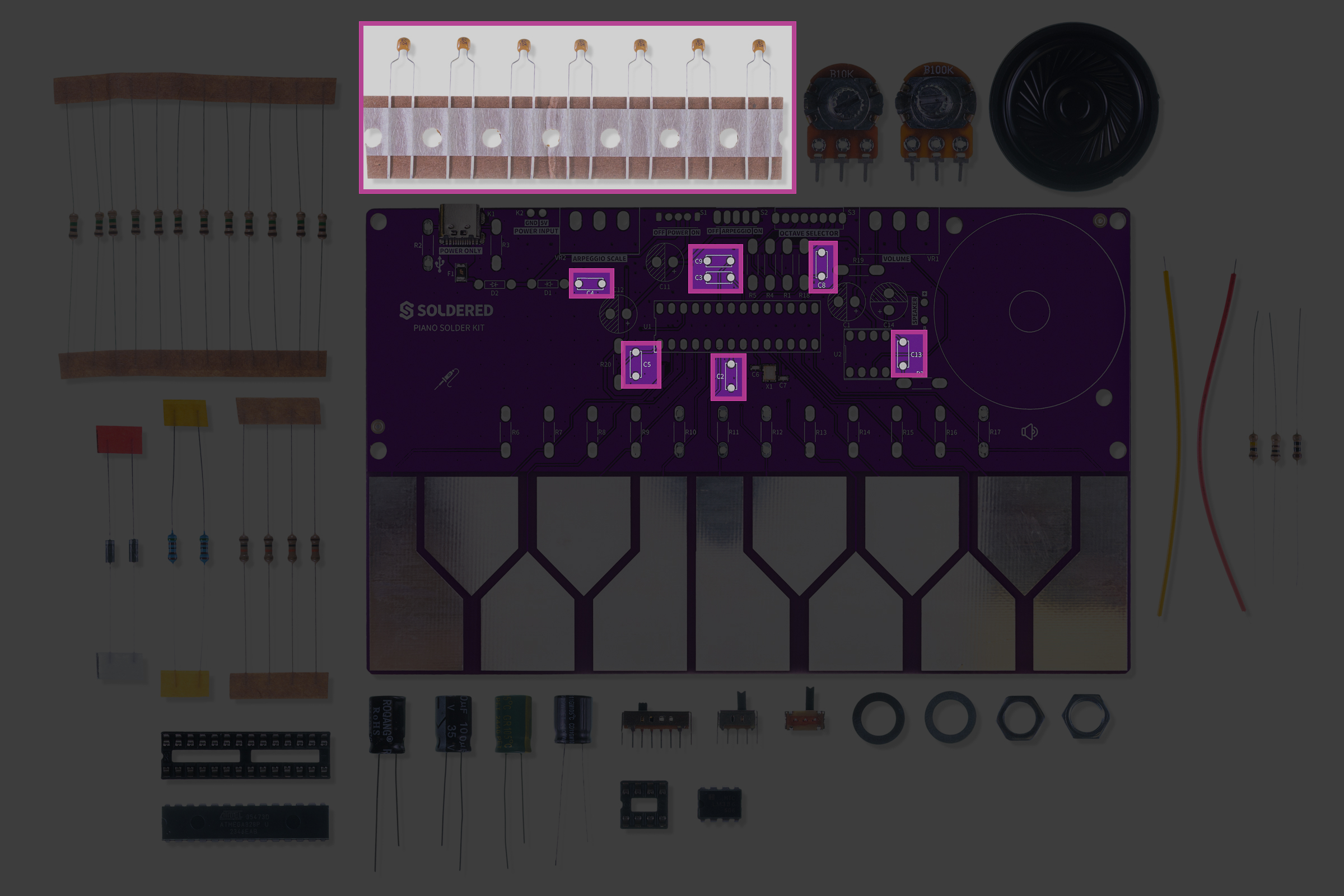
Step 6: Solder the 100 nF capacitors
These capacitors come pre-bent and are easy to insert.
They are non-polarized, so their orientation doesn’t matter.
Placement table:
| Capacitor | Value | Position on PCB |
|---|---|---|
| C13, C4, C5, C2, C8, C3, C9 | 100 nF | Decoupling capacitors |
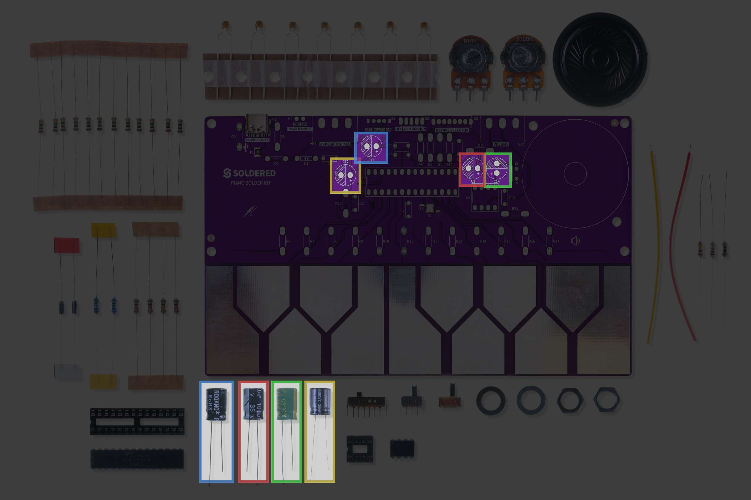
Step 7: Solder the electrolytic capacitors
These capacitors are polarized, so mind their orientation!
You can identify their values by reading the labels on the side. The shorter leg is the cathode and is marked by the lighter color stripe on the casing. The 680 µF capacitor is also green-colored.
The cathode (shorter leg) must be inserted into the shaded pad, and the anode (longer leg) into the pad marked with a + sign.
Placement table:
| Capacitor | Value | Notes |
|---|---|---|
| C1 | 100 µF | Power filtering |
| C11 | 100 µF | Audio path |
| C12 | 10 µF | Signal coupling |
| C14 | 680 µF | Output capacitor (green) |
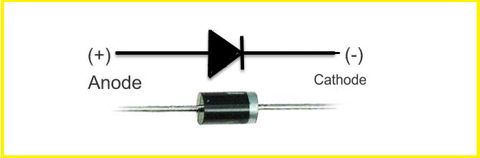
Step 8: Solder the diodes
The diodes in the package are identical and go into D1 and D2 — but mind their orientation!
To place the diode correctly, keep in mind the white marked side of the diode is the cathode.
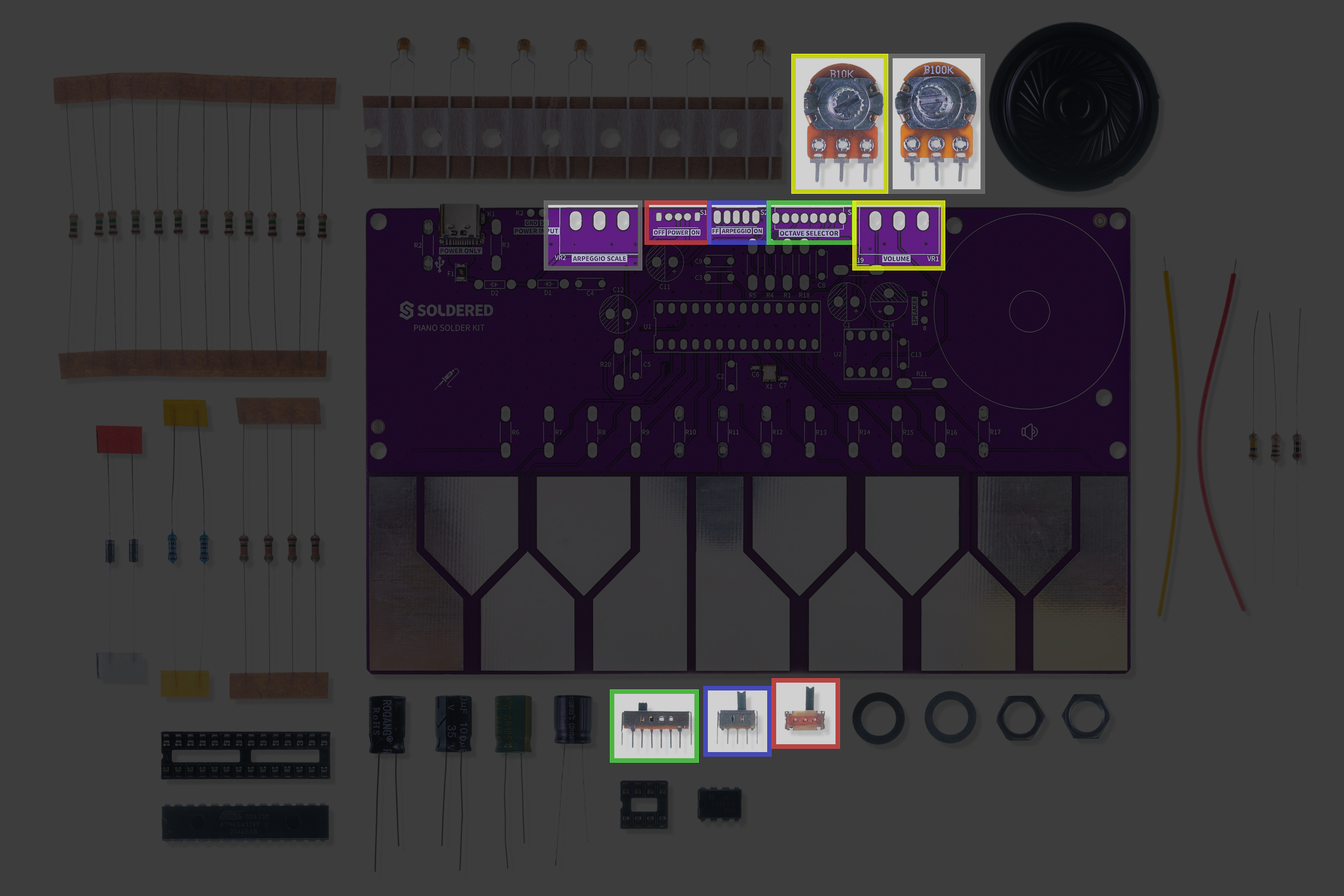
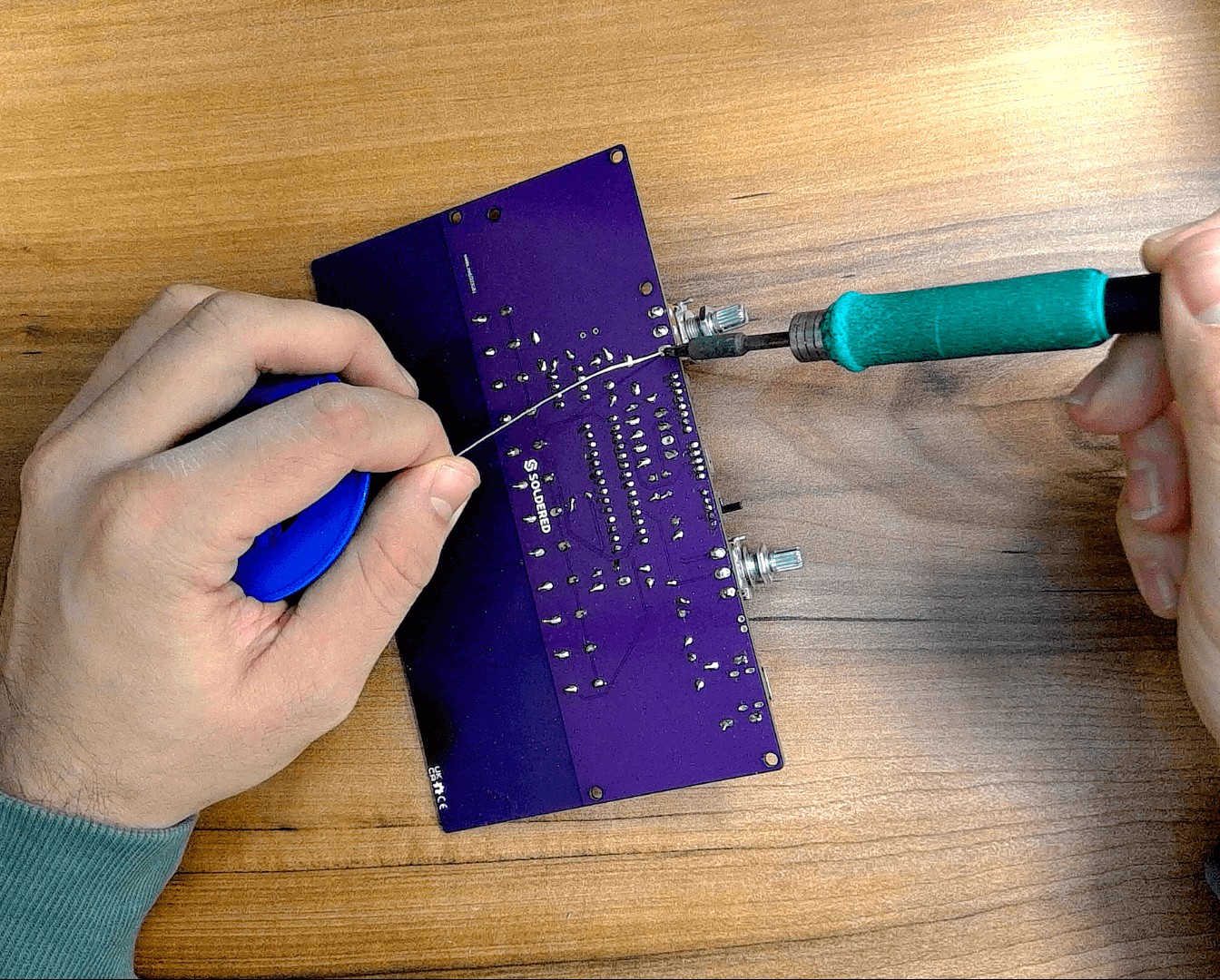
Step 9: Solder the potentiometers and switches
Almost there! Let’s solder the mechanical parts.
Potentiometers:
| Label | Value | Function |
|---|---|---|
| VR1 | 10 kΩ | Volume control |
| VR2 | 100 kΩ | Tone control |
The switches only fit one way in their respective slots (ON/OFF, octave selection, and arpeggio mode).
Step 10: Finish the build
Solder and attach the speaker wires to the speaker, then connect them to the speaker outputs on the board.
The speaker includes a small piece of self-adhesive tape to attach it to the PCB.
Then, you can insert the ICs into their sockets — mind their orientation!
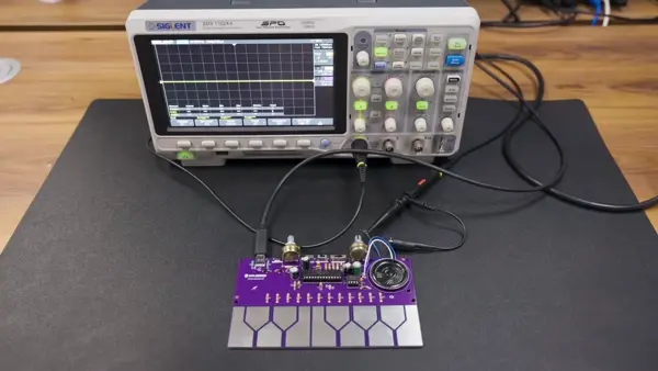
Ready to go!
Now, simply plug it into USB-C and play!