Rfid – How it works
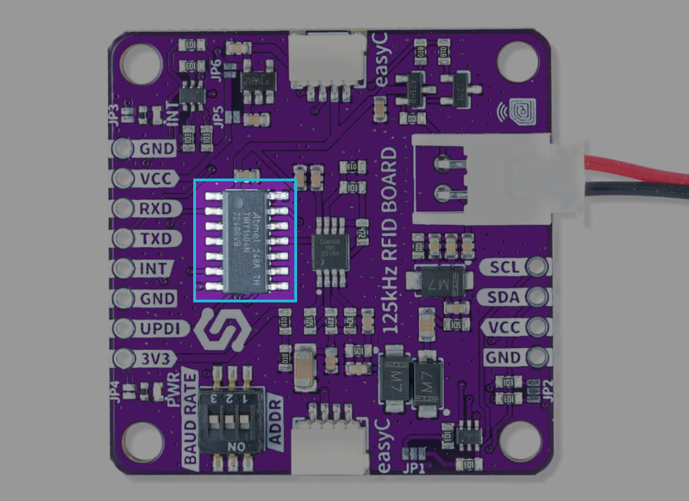
The 125kHz RFID Tag Reader Board is a compact and efficient module designed for reading RFID tags operating at 125kHz. It is ideal for applications such as access control, personal identification, security systems, and interactive projects. It operates using its ATTINY1604 chip to read cards.
How the RFID reader works
The RFID reader operates by detecting the presence of a compatible 125kHz tag near its antenna. The tag receives power wirelessly through electromagnetic waves emitted by the reader's antenna. Once powered, the tag transmits its unique code to the RFID reader, where it is decoded and sent to a microcontroller via UART communication.
The module supports a reading distance of 2–5 cm, ensuring reliable performance in close-range applications. It uses 125kHz-compatible read-only or read/write tags, making it suitable for various identification and control systems.

UART communication
The 125kHz RFID Tag Reader Board UART version supports UART communication to send data to a microcontroller. The module operates at a baud rate of 115200 bps with TTL-level RS232 format, ensuring fast and reliable data transmission.
Pinout:
| Pin Name | Function | Notes |
|---|---|---|
| TX | Transmit Data | Sends tag data to the microcontroller. |
| RX | Receive Data | Receives commands from the microcontroller (optional). |
I2C Communication
The 125kHz RFID Tag Reader Board I2C version supports I2C communication, allowing seamless integration with microcontrollers. This variant is ideal for applications requiring multiple devices on the same bus or low pin usage.
Pinout:
| Pin Name | Function | Notes |
|---|---|---|
| SDA | Data Line | Connect to the microcontroller's I2C data pin. |
| SCL | Clock Line | Connect to the microcontroller's I2C clock pin. |
Measurement process
-
Power-up and Initialization
- Connect the module to a 5V power supply and ensure proper grounding.
- Initialize UART communication at 115200 bps on your microcontroller.
-
Tag Detection
- Place a compatible 125kHz RFID tag near the antenna (within 2–5 cm).
- The tag powers up via electromagnetic waves and starts transmitting its unique code.
-
Data Retrieval
- The module sends the tag's code through its TX pin.
- Use UART commands on your microcontroller to read and process the transmitted data.
-
Code Decoding
- Decode the received data using software logic to extract meaningful information such as the tag ID or serial number.