Assembly guide
On this page, we will guide step by step on how to assemble this kit.
Step 1: Solder the resistors to the PCB.
Use a multimeter to differentiate resistor based on their resistance value. Start by putting the multimeter in resistance measuring mode and connect the multimeter's probes to the ends of the resistor, separate them based on the resistance value.
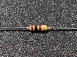
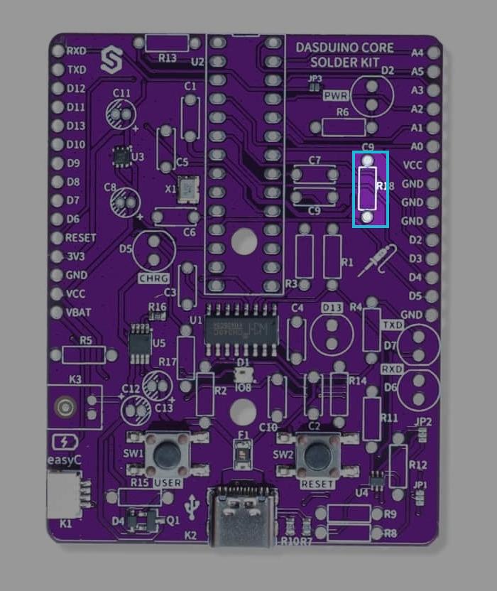
Solder the 100 Ohm resitors
Solder the 100Ohm resistors to the bpc on pins marked R18. Their orientation doesn't matter.
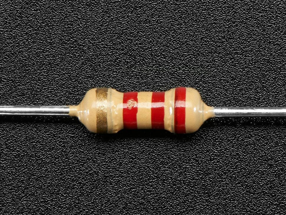
Find the resistors with markings as shown below:
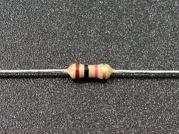
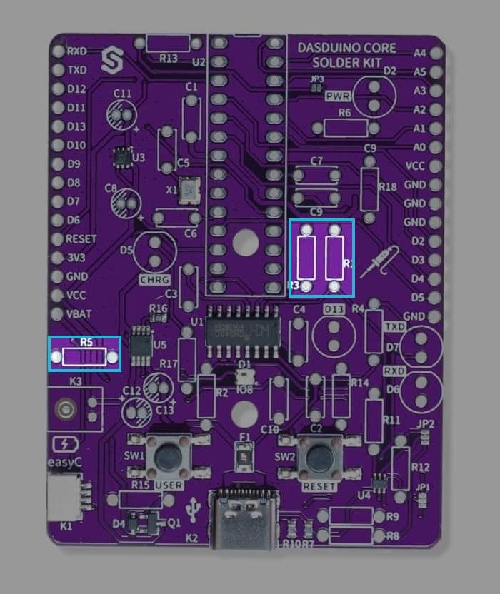
Solder the 1k Ohm resistors
Solder the 1kOhm resistors to the pbc on pins marked R1, R3, R5. Their orientation doesn't matter.
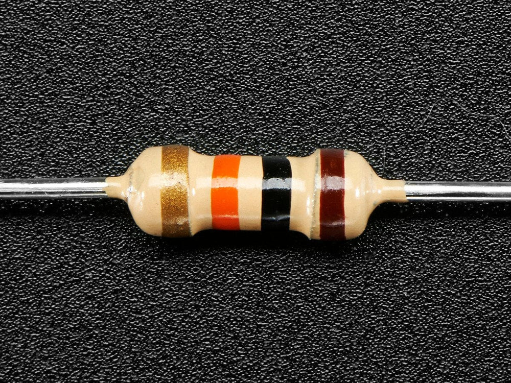
Find the resistors with markings as shown below:
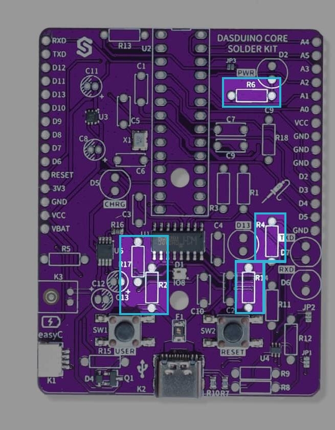
Solder the 2.2k Ohm resistors
Solder the 2.2kOhm resistors to the pcb on pins marked R2, R4, R6,R14,R17. Their orientation doesn't matter.
Find the resistors with markings as shown below:
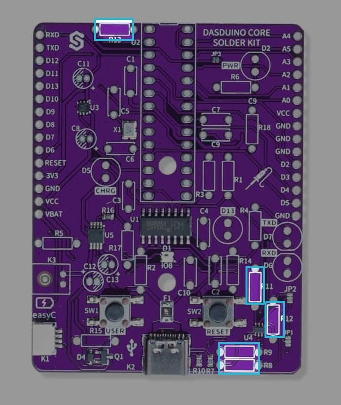
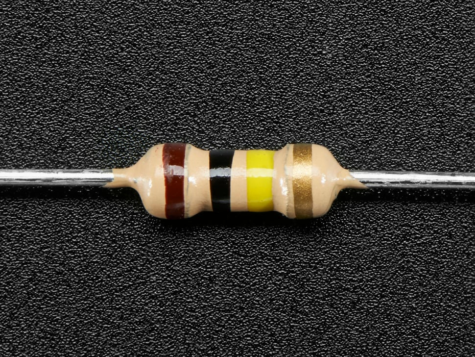
Solder the 10k Ohm resistors
Solder the 10kOhm resistors to the pcb on pins marked R8, R9, R11,R12,R13. Their orientation doesn't matter.
Find the resistors with markings as shown below:
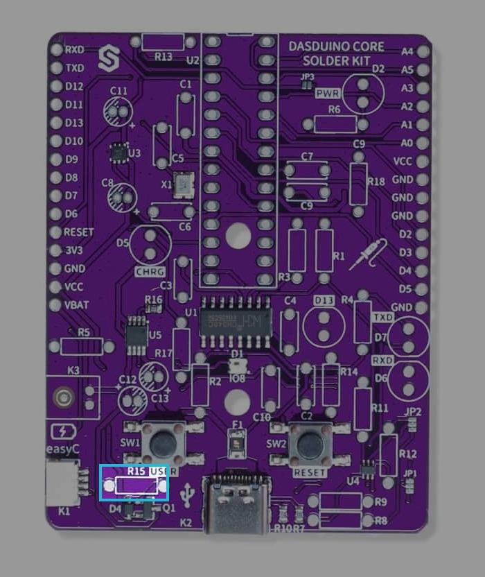
Solder the 100k Ohm resitors
Solder the 100Ohm resistors to the bpc on pins marked R15. Their orientation doesn't matter. Find the resistors with markings as shown below:
Step 2: Solder the capacitors
Use a multimeter to differentate capacitors based on their capacitance value. Start by putting the multimeter in capacitance measuring mode and connect the multimeter's probes to the ends of the capacitor, separate them based on the capacitance value.
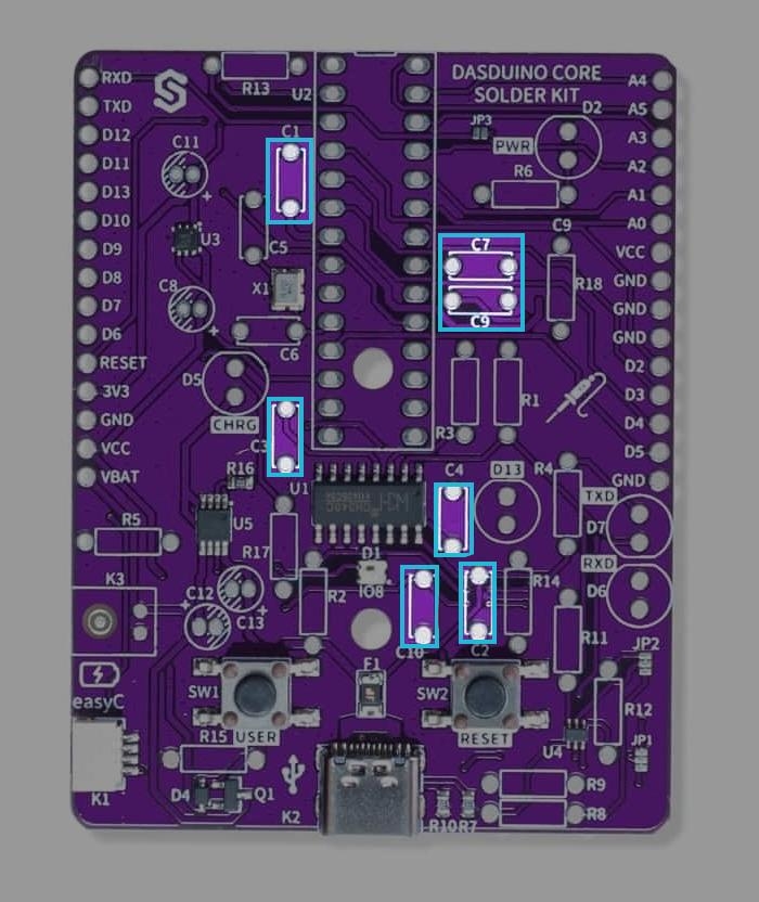
Solder the 100nF capacitors
Solder the 100nF capacitors to the pcb on pins marked C1,C2,C3,C4,C7,C9,C10. These capacitors are non-polarized capacitors, which means that their orientation doesn't matter.
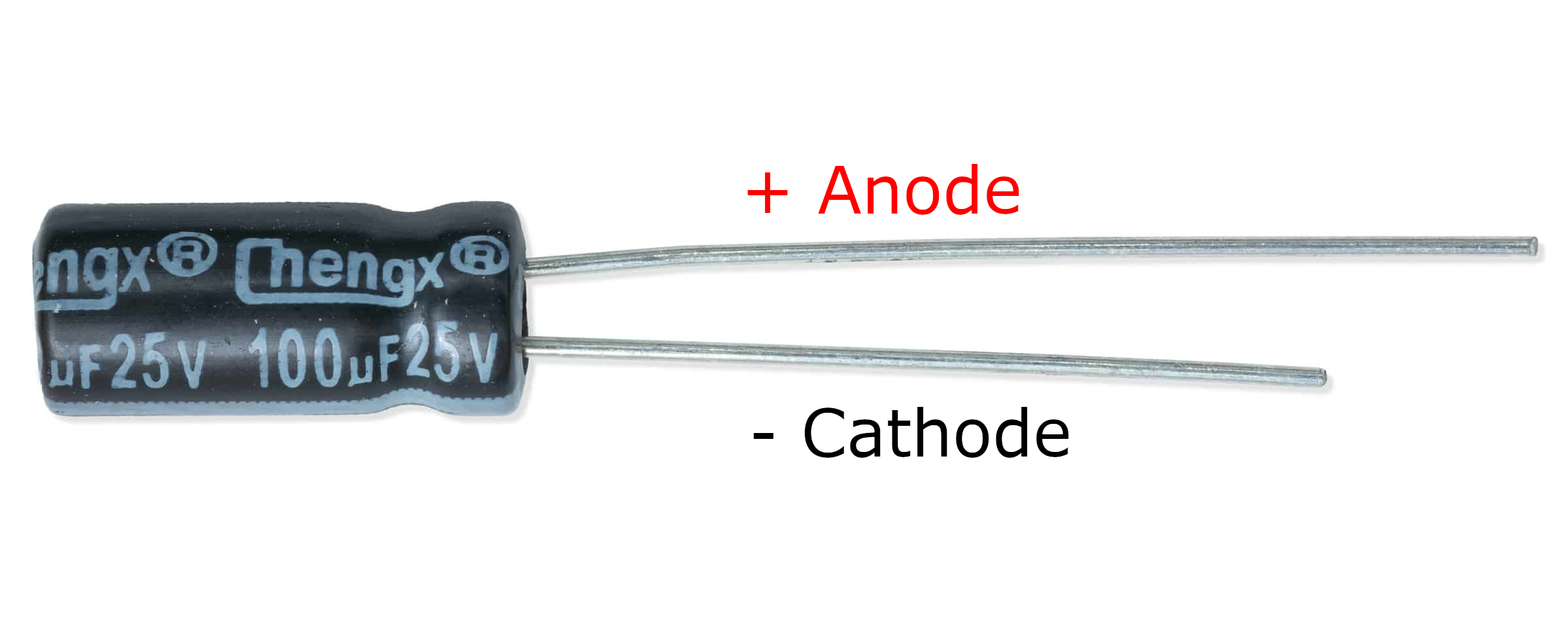
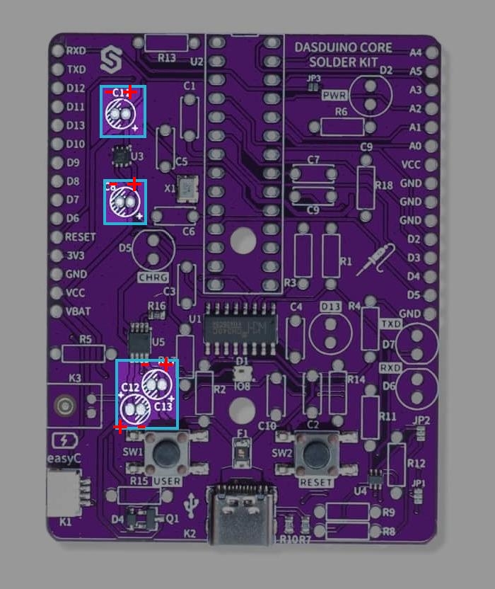
Solder the 2.2uF capacitors
Solder the 100nF capacitors to the pcb on pins marked C8,C11,C12,C13. These capacitors are polarized capacitors, which means that their anode (+) must be soldered to + marked side on pins.
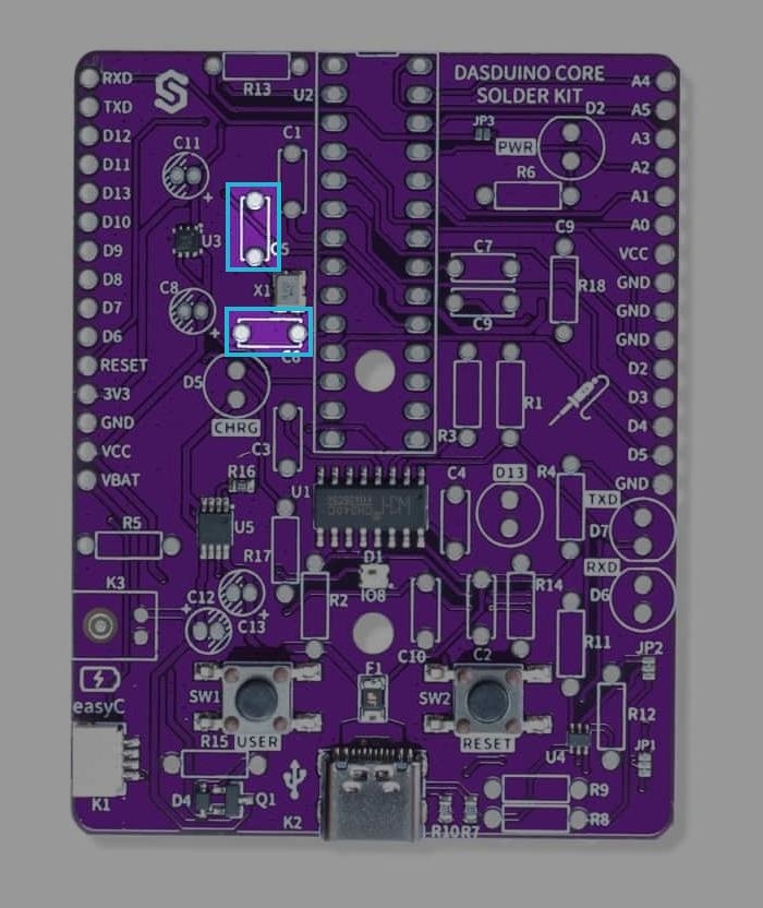
Solder the 22pF capacitors
Solder the 100nF capacitors to the pcb on pins marked C5,C6. These capacitors are non-polarized capacitors, which means that their orientation doesn't matter.
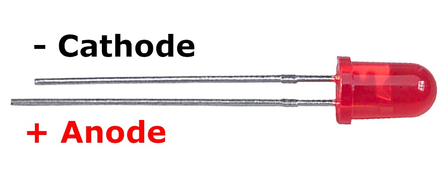
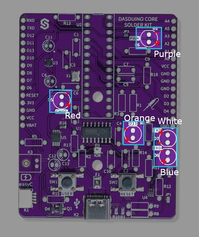
Step 3: Solder the LEDs
Solder the LEDs to the pcb in the order provided below:
| LED Color | Pin number |
|---|---|
| Purple | D2 |
| Red | D5 |
| Blue | D6 |
| White | D7 |
| Orange | D13 |
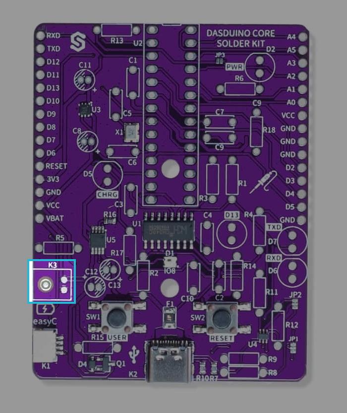
Step 4: Solder the JST battery connector
Solder the JST battery connctor to the pcb on pins marked K3, make sure that the connector covers it's drawn topology (That it's facing outwards).
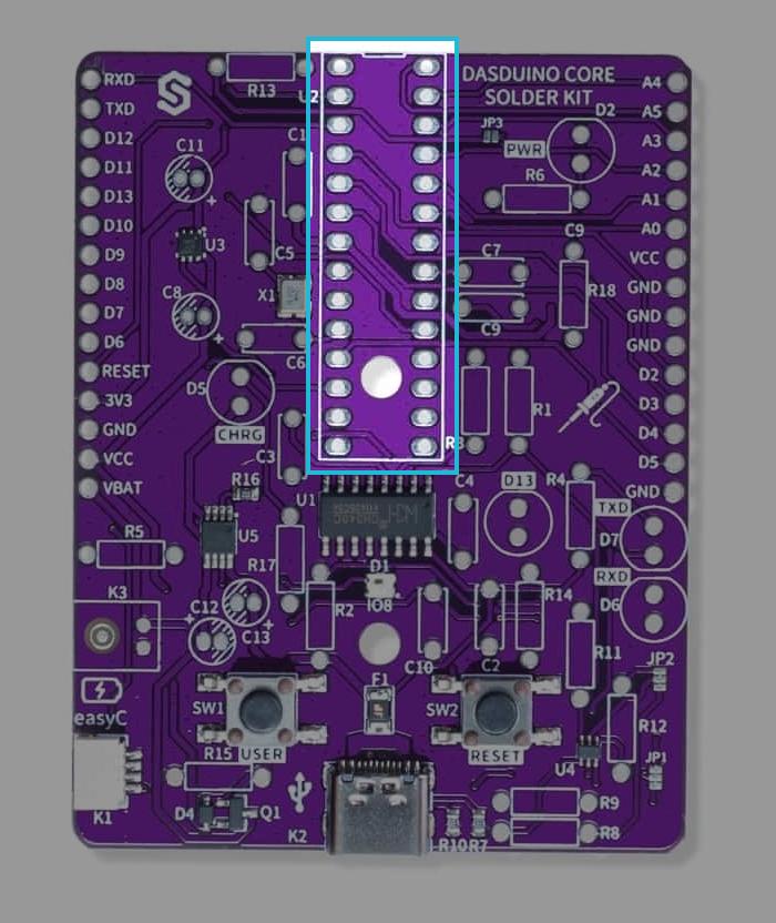
Step 5: Solder the ATmega328P Socket
Solder the socket to the pbc on pins marked U2 (its drawn topology).