Stepper Motor Driver - How it works
On this page, let's go over how this breakout board actually drives a stepper motor.
This is a simple stepper motor driver breakout board designed to control a bipolar or unipolar stepper motor using signals from a microcontroller. The board operates by switching the motor coils on and off in a controlled sequence to achieve precise rotational motion. The microcontroller generates pulses on the IN1–IN4 input pins, which are then used to switch NPN transistors that control the motor’s windings.
Stepper Motor Basics
A stepper motor is a type of motor that moves in discrete steps rather than continuous rotation like a DC motor. It does this by energizing different coils (or phases) in a sequence. There are two main types of stepper motors:
- Bipolar stepper motors have two coils and require H-bridge control to reverse the direction of current flow in each coil. This breakout board provides that control using four NPN transistors to switch the motor windings.
- Unipolar stepper motors have a center tap on each coil, allowing them to be driven more simply, though they are less efficient. This driver can also be used with unipolar stepper motors by only energizing one side of each coil at a time.
Driving the Stepper Motor
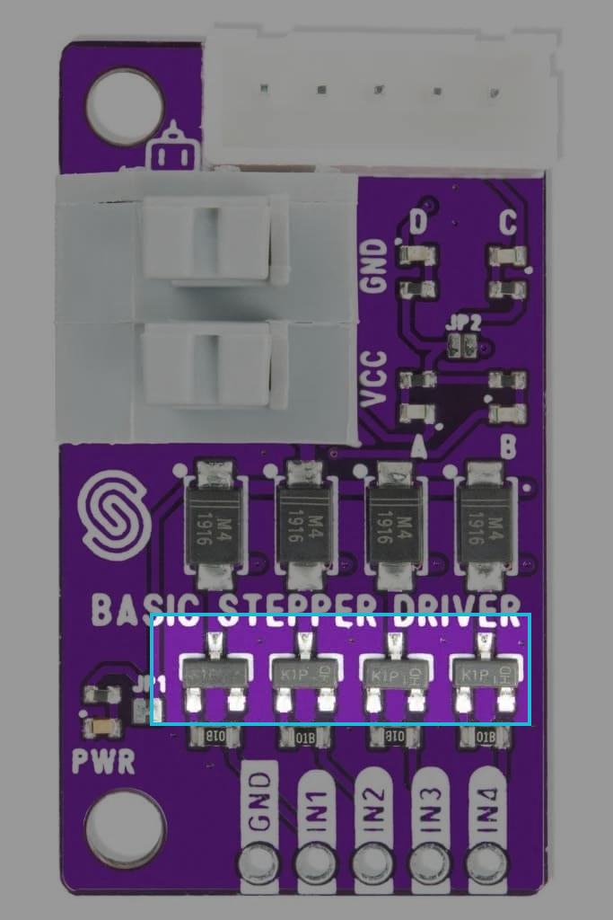
The IN1–IN4 pins on the board serve as control inputs. These pins are connected to the base of NPN transistors via 1k resistors. The transistors act as switches that allow current to flow through the motor coils when activated. When a pulse is applied to an IN pin, the corresponding transistor turns on, allowing current to flow from VCC through the motor winding to ground. This sequential activation of the transistors causes the stepper motor to move step by step.
See below for a visualization and chart of how these different coils take turns in activating:


Output LEDs
To help visualize the stepper motor operation, each transistor output is accompanied by an LED indicator. These LEDs light up when the corresponding transistor is activated, providing a real-time indication of which coil is currently energized. To activate the LED lights, JP2 must be bridged!
Stepper Motor Control Sequence
A stepper motor is controlled by sending pulses to the IN1–IN4 pins in a specific sequence. Different Arduino libraries support different stepping modes:
- Full-step mode: Energizes two coils at a time for higher torque.
- Half-step mode: Alternates between energizing one and two coils at a time, providing smoother movement.
- Microstepping mode: Uses precise control of current to allow finer resolution.