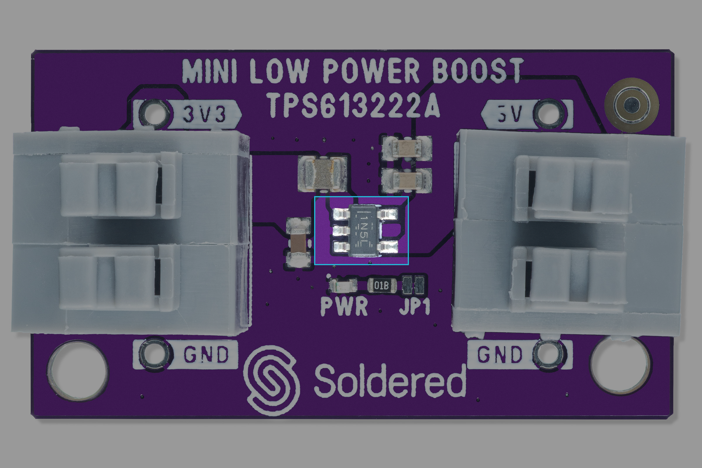
TPS61322A - How it works
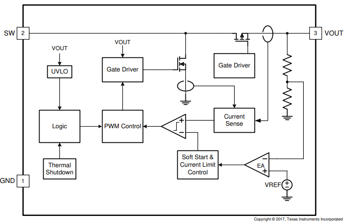
The TPS613222A is a synchronous boost converter with only 6.5 µA quiescent current. It provides a power-supply solution for products powered by an alkaline battery, a NiMH rechargeable battery, or a one-cell Li-ion battery. The boost converter is based on a hysteretic control topology using synchronous rectification to obtain maximum efficiency at minimal quiescent current. The TPS61322 also allows the use of a small external inductor and capacitors. Higher than 90% efficiency is achieved at a 10 mA load from 1.5 V input to 2.2 V output conversion.
The output voltage is set internally to a fixed output voltage from 1.8 V to 5.5 V in increments of 0.1 V. Thus, it only needs two external components to achieve the desired output voltage. The TPS61322 also implements a thermal shutdown protection function.
Datasheet
For an in-depth look at technical specifications, refer to the official DW01x Datasheet:
TPS613222A Datasheet
Detailed technical documentation for the TPS613222A boost converter
How It Works
Soft Start
When the input voltage is applied, the high-side MOSFET is turned on. The input voltage charges the output capacitors through the inductor and the high-side MOSFET. When the output capacitors are charged to a typical value of 0.83 V, the TPS61322xx starts switching at a fixed frequency of 1.6 MHz and the high-side MOSFET is turned off. When the output voltage rises to the typical value of 1.6 V, an internal soft-start control circuit ramps the reference voltage to 0.8 V within 2 ms. In this way, the soft-start function reduces the input inrush current. After the output voltage reaches the target value, the soft start ends, and the inductor peak current is determined by the output of an internal error amplifier.
Boost Controller Circuit
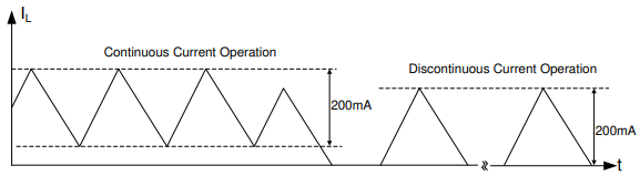
The TPS61322xx boost converter is controlled by a hysteretic current mode scheme. The TPS61322xx regulates the output voltage by maintaining a constant inductor ripple at a typical value of 200 mA and adjusting the offset of this inductor current depending on the output load. If the required average input current is lower than the average inductor current defined by this constant ripple current, the inductor current becomes discontinuous to keep the efficiency high under light load conditions. The output voltage VOUT is monitored via the internal feedback network connected to a voltage error amplifier. To regulate the output voltage, the voltage error amplifier compares this feedback voltage to the internal voltage reference and adjusts the required offset of the inductor current accordingly.