Adc – How it works
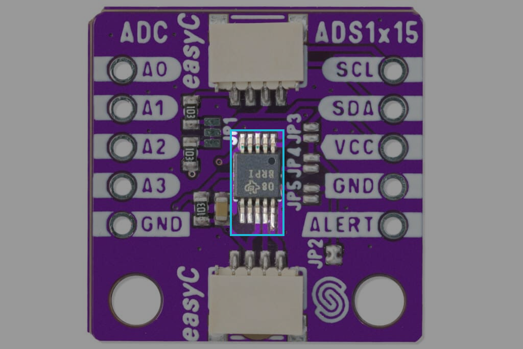
The ADS1015/ADS1115 are low-power, high-precision 12-bit (ADS1015) and 16-bit (ADS1115) analog-to-digital converters manufactured by Texas Instruments with programmable gain and an integrated I2C interface, offering easy integration for accurate analog signal conversion in embedded systems.
Datasheet
For an in-depth look at technical specifications, refer to the official ADS1x15 Datasheet:
ADC 12-bit ADS1015 Datasheet
Detailed technical documentation for the ADC ADS1015
ADC 16-bit ADS1115 Datasheet
Detailed technical documentation for the ADC ADS1115
How It Works
The ADS1015 and ADS1115 are delta-sigma (ΔΣ) analog-to-digital converters (ADCs) designed for precise, low-power, and noise-free conversions. These devices convert analog signals into digital values that can be processed by microcontrollers, with a strong emphasis on eliminating common-mode noise and ensuring accurate measurements.
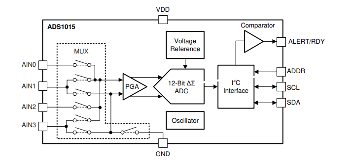
The core of the ADCs measures a differential input, with the voltage difference between two input pins: AINP (positive input) and AINN (negative input). This differential signal, VIN, is passed through a switched-capacitor ΔΣ modulator that converts the analog input into a high-speed bitstream. The bitstream is then processed by a digital filter, which outputs a final digital code proportional to the input voltage. This differential architecture helps attenuate common-mode signals, making the devices ideal for accurate measurements in noisy environments.
The ADS1015 and ADS1115 provide two operating modes: single-shot mode and continuous-conversion mode. In single-shot mode, the ADC performs one conversion when triggered, stores the result in an internal register, and enters a power-down state. This mode is well-suited for systems requiring periodic measurements, as it conserves power between conversions. In continuous-conversion mode, the ADC continuously performs conversions at the programmed data rate. After each conversion is completed, the ADC immediately begins the next conversion, ensuring that data is always up-to-date.
Both the ADS1015 and ADS1115 include several programmable features that enhance flexibility. The programmable gain amplifier (PGA) (available in the ADS1015 and ADS1115, except the ADS1113) allows adjustment of the input signal’s gain, making it adaptable to various signal amplitudes. Additionally, the programmable digital comparator (available in the ADS1114 and ADS1115) enables users to set a voltage threshold. When the input signal exceeds or falls below this threshold, the comparator triggers an alert on the ALERT pin, providing an interrupt signal to the microcontroller.
I2C Communication Protocol
The ADS1015 and ADS1115 communicate via the I2C interface, allowing for easy integration with microcontrollers. Key features of the I2C protocol are:
- Addressing: The devices support four selectable I2C addresses, allowing multiple devices to be used on the same bus.
- Data Read/Write: Data is transferred using standard I2C commands to configure the ADC, start conversions, and read conversion results.
- Clock Speed: The devices support standard I2C speeds (100 kHz, 400 kHz) for reliable communication.
- Register Map: Configuration and data are accessed via a well-defined register map, allowing full control over conversion settings, input channels, and comparator functionality.
This I2C interface simplifies integration and communication with microcontrollers in embedded systems.