Electrochemical Gas Sensors – How it works
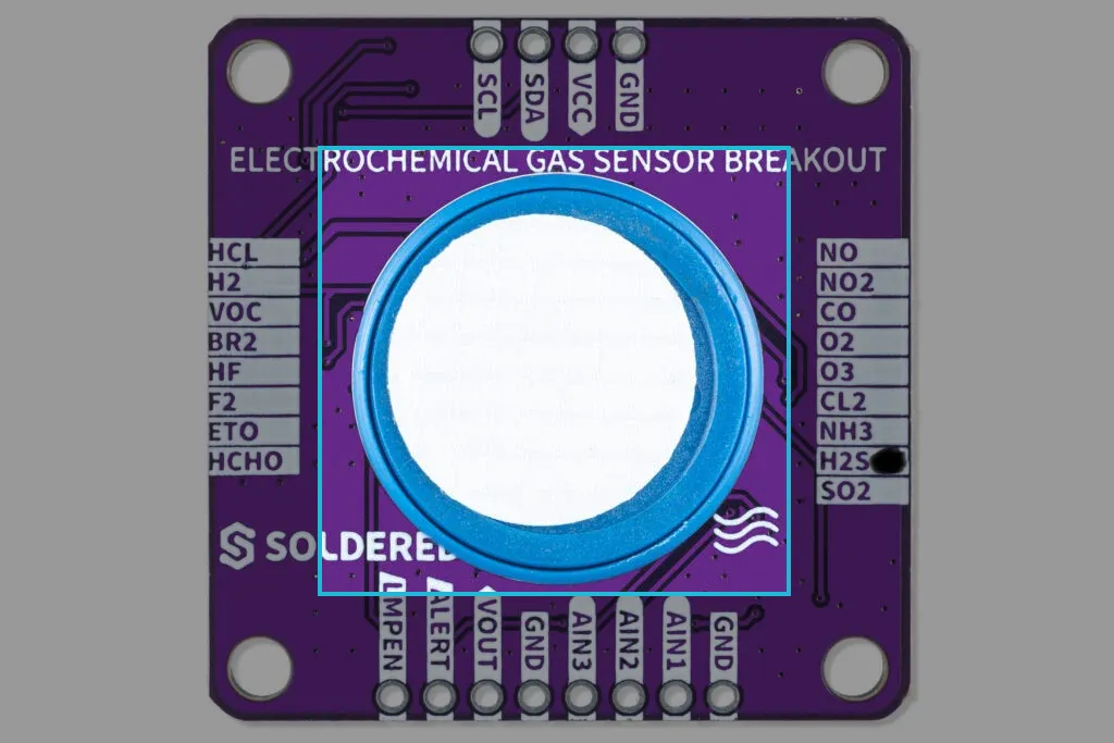
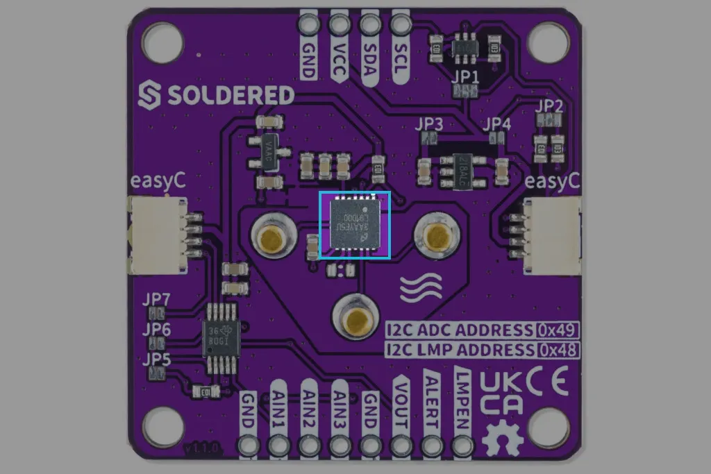
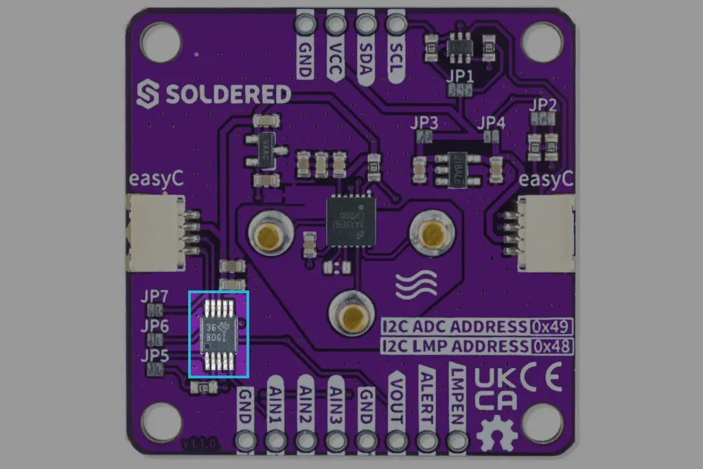
The breakout board consists of a sensor by SGX. For the sensor to maintain its bias, a potentiometer is needed. For that, we are using the LMP91000 by Texas Instruments. Finally, to get readings that can be sent via I2C, we are using the ADS1115IDGS analog-to-digital converter by Texas Instruments.
Datasheet
LMP91000 Datasheet
Detailed technical documentation for the LMP91000 potentiometer
ADS1115IDGS Datasheet
Detailed technical documentation for the ADS1115IDGS
How the sensor works
Electrochemical sensors use a chemical reaction to measure the concentration of specific gases in various environments. They work by reacting with the gas of interest and producing an electrical signal proportional to the gas concentration. The sensor operates by allowing charged molecules to pass through a thin layer of electrolyte.
How the LMP91000 works
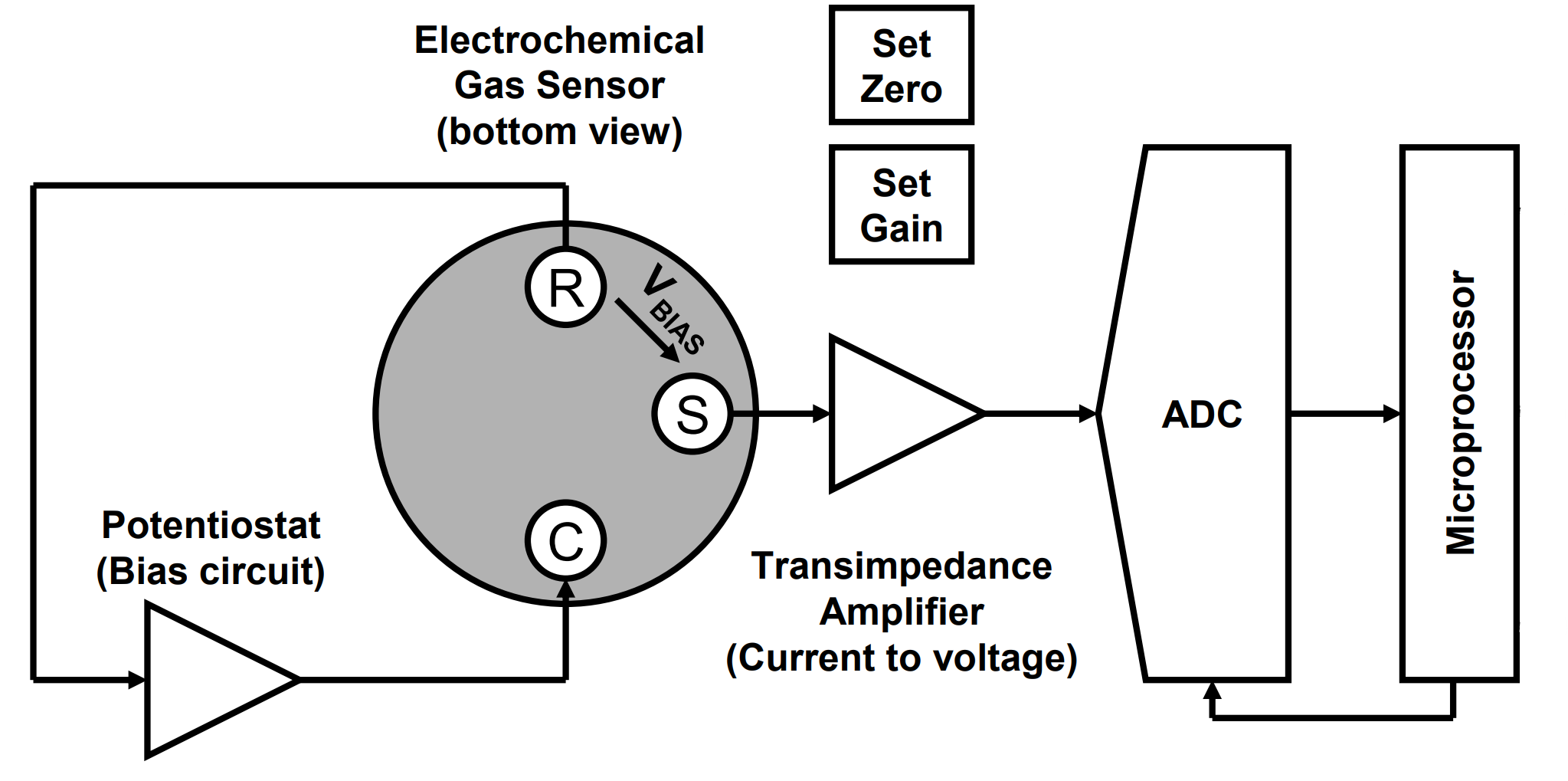
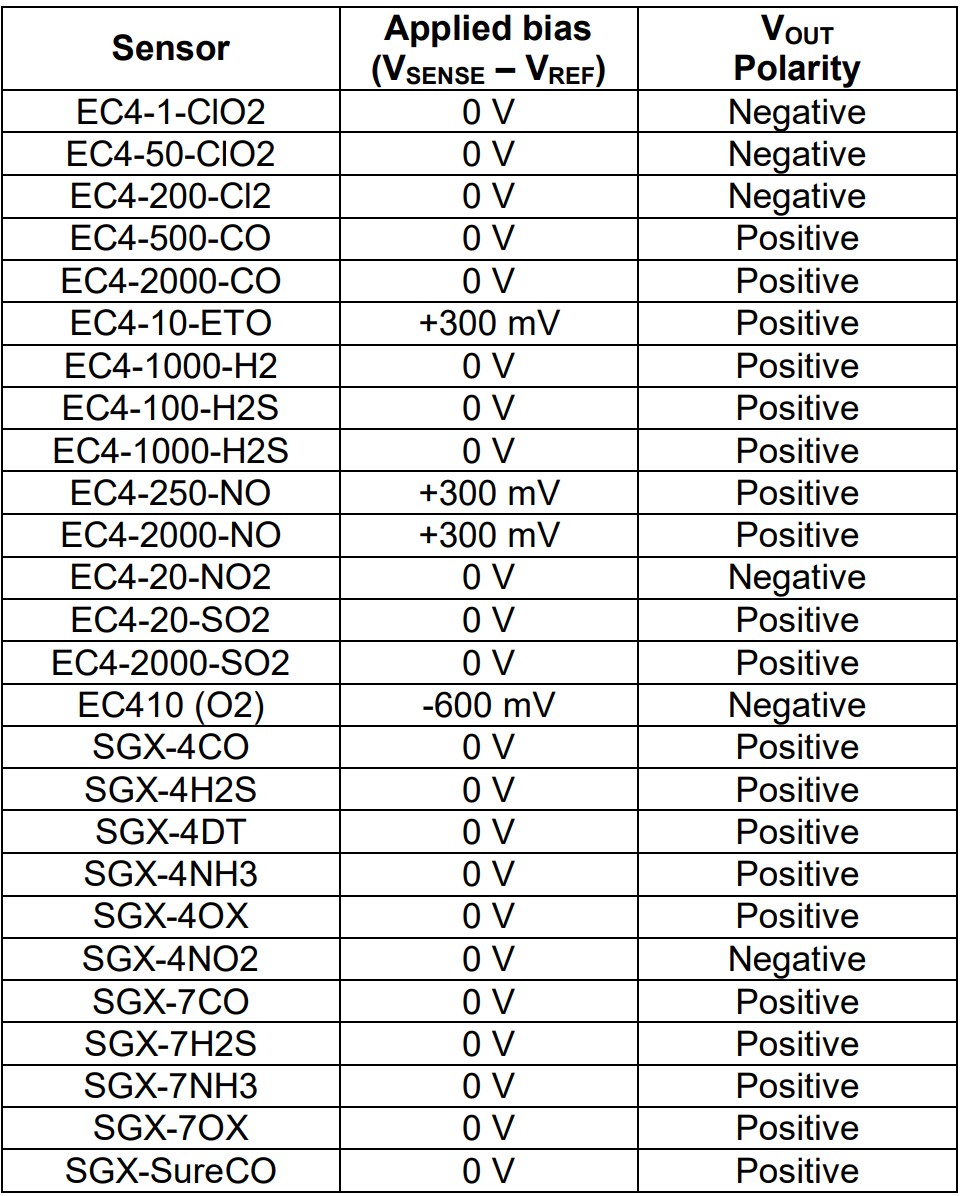
The electrochemical gas sensor requires a bias circuit known as a potentiostat to maintain the correct bias potential between the sensing and reference electrodes, as stated on the individual sensor datasheet:
The gas sensor produces an output current proportional to the gas concentration. A current-to-voltage converter, also known as a trans-impedance amplifier, is required to convert the small currents from the electrochemical cell into a useful voltage for measurement.
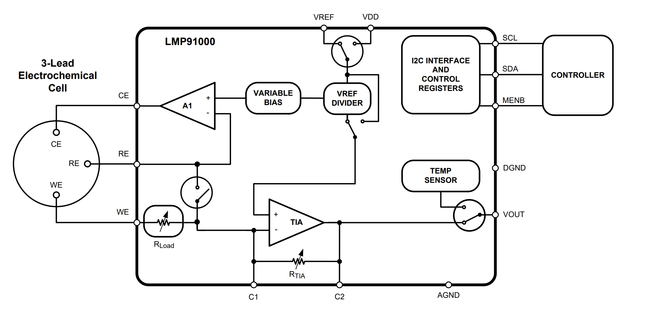
The LMP91000 is a programmable analog front-end (AFE) for use in micro-power electrochemical sensing applications. It provides a complete signal path solution between a sensor and a microcontroller that generates an output voltage proportional to the cell current.
The core of the LMP91000 is a potentiostat circuit. It consists of a differential input amplifier used to compare the potential between the working and reference electrodes to a required working bias potential (set by the Variable Bias circuitry). Any changes in the impedance between the working and reference electrodes will cause a change in the voltage applied to the counter electrode to maintain the constant voltage between them. A Transimpedance Amplifier connected to the working electrode is used to provide an output voltage that is proportional to the cell current. The working electrode is held at virtual (internal) ground by the transimpedance amplifier. The potentiostat compares the reference voltage to the desired bias potential and adjusts the voltage at the counter electrode to maintain the proper working-to-reference voltage.
The transimpedance amplifier (TIA) converts the output current of the electrochemical sensor into a voltage that is easily read by a microcontroller. By changing the value of the Rtia resistor, we can adjust the sensitivity of the sensor to suit our needs.
The internal Zero is the voltage at the non-inverting pin of the TIA. The internal zero can be programmed to be either 67%, 50%, or 20% of the supply, or set to the external reference voltage.
The Variable Bias circuitry provides the bias voltage required by a gas sensor between its reference and working electrodes.
After going through the potentiostat and trans-impedance amplifier, the voltage (VOUT) is outputted to the ADS1115 so it can be converted to a digital signal.
How the ADS1115 works
Since we are communicating with the board via I2C, the analog output we get from the LMP91000 must be converted into a digital signal.
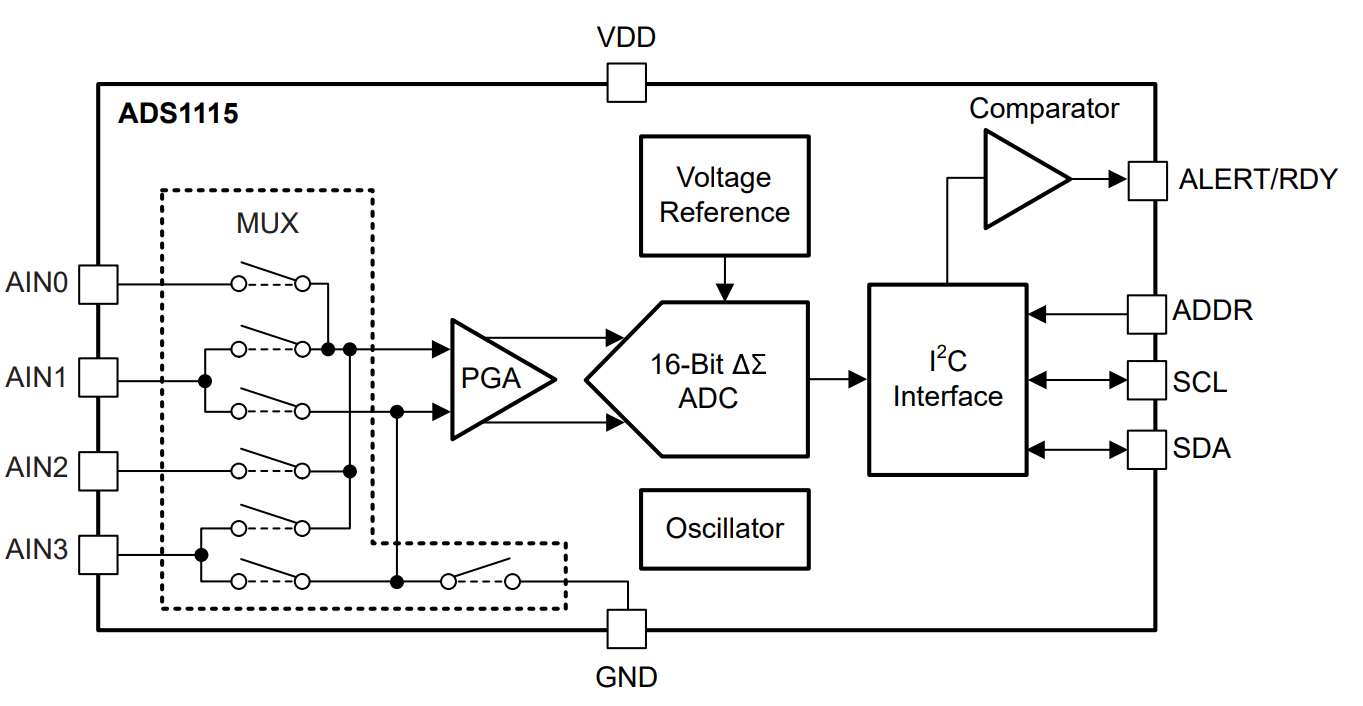
The ADS1115 is a 16-bit precision analog-to-digital converter (ADC) that measures small single-ended voltage signals using an internal programmable gain amplifier (PGA) and a sigma-delta modulator. It communicates via I2C and features four input channels, a reference voltage, and an onboard oscillator. The ADC samples the input voltage, compares it to the reference, and converts it into a digital value through oversampling and noise shaping.
I2C communication
When using our breakout board, you communicate with the LMP91000 and the ADS1115 independently. Both devices have a unique, predefined I2C address (0x48 and 0x49, respectively).
When initializing the sensor, we send the configuration data defined by the library or a user-configured one.
When we want to read a measurement from the sensor, we read the output of the ADS1115.