Hall Effect Sensor – How it works
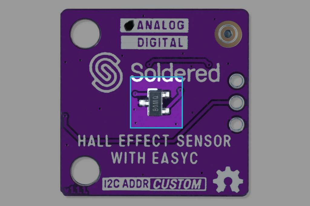
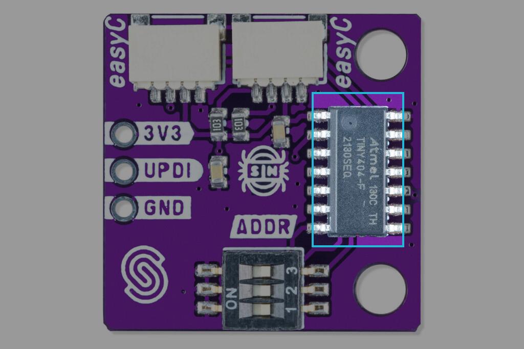
Analog versions of the circuit board (both regular and Qwiic) use the SI7211-B-00-IV sensor, while digital (both regular and Qwiic) use SI7211-B-06-IV sensor by Silicon Labs. When using a Qwiic version you are essentially communicating with an onboard ATTINY404 MCU via I2C communication.
Datasheet
For an in-depth look at technical specifications, refer to the official SI7211-B-00-IV / SI7211-B-06-IV Datasheet:
SI721x Datasheet
Detailed technical documentation for the SI721x sensors
How the sensor works
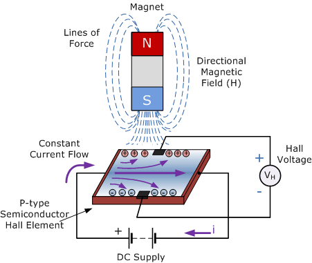
A SI721x consists of a thin rectangular semiconductive material (indium arsenide, gallium arsenide) through which flows a continuous current. When the sensor is exposed to a magnetic field perpendicular to the current, the magnetic (Lorentz) force deflects the charge carriers within the semiconductor. This deflection causes a difference in potential, known as Hall Voltage, which is proportional to the strength of the magnetic field. The Hall Voltage generated is typically very small (in microvolts), so it is amplified by an internal high gain amplifier.
I2C communication - Qwiic
Qwiic versions of the product use an onboard ATTINY404 MCU to implement I2C communication. The breakout board operates with a default I2C address of 0x30; however, this can be changed using the onboard switches. To change the breakout board's address, check the Address selection. When detected, the ATTINY404 receives data from the sensor and passes it on to the main MCU using the I2C data line. To check in detail how the ATTINY404 is preprogrammed, check the firmware github page.