Led Matrix – How it works
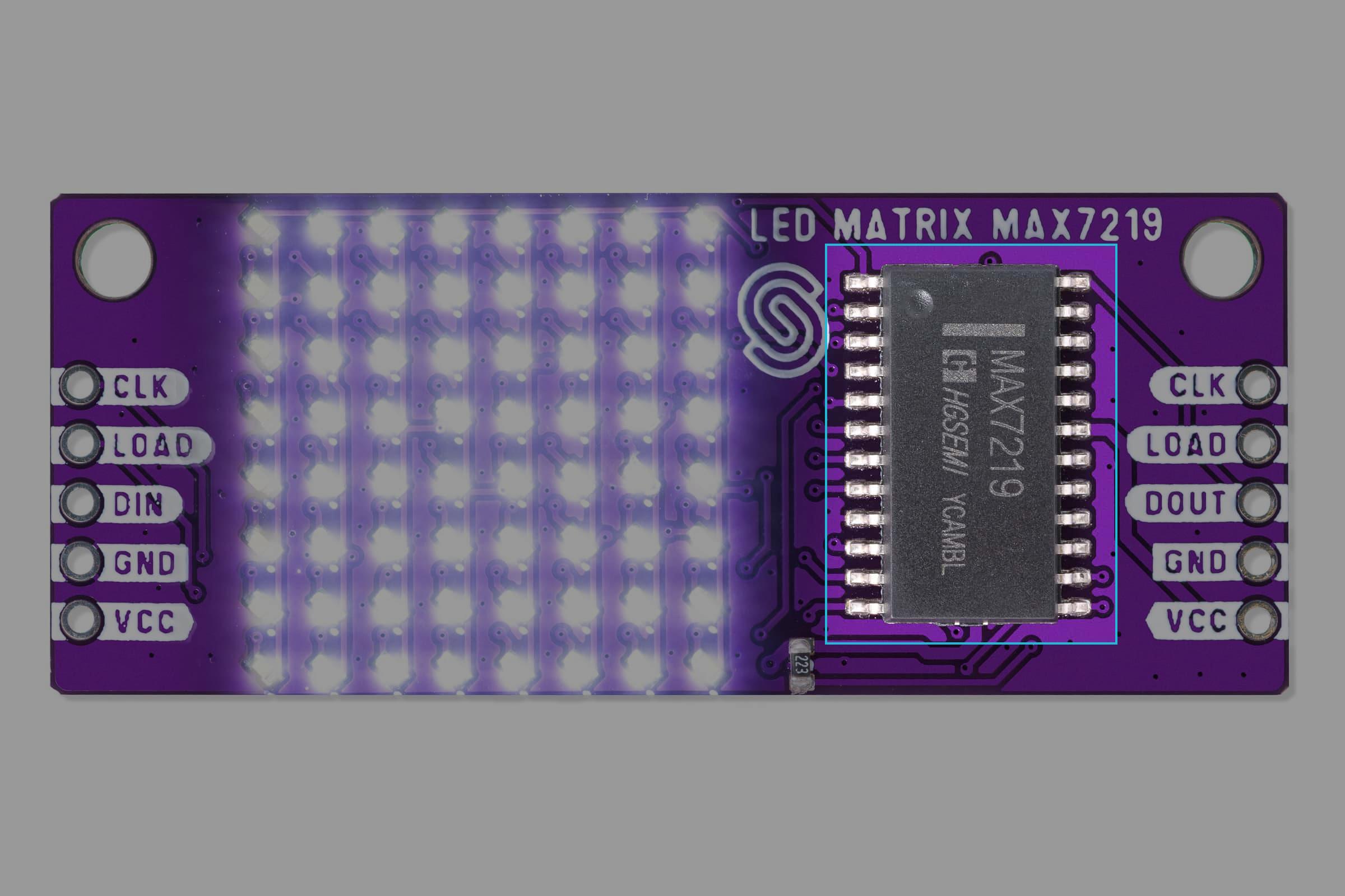
The LED matrix is a circuit board that contains a system of 64 interconnected LEDs that are controlled by onboard MAX7219 LED driver by Adafruit.
Datasheet
For an in-depth look at technical specifications, refer to the official MAX7219 Datasheet:
MAX7219 Datasheet
Detailed technical documentation for the MAX7219 LED driver
How the driver works
The MAX7219 uses a 3-wire SPI-compatible protocol with DIN (data in), CLK (clock), and LOAD (chip select) pins. Data is shifted into the chip, controlling the LED states through an internal shift register. The driver can control up to 8 digits of a 7-segment display or an 8x8 LED matrix. It achieves this through multiplexing , meaning it quickly switches between LED segments to make them appear continuously lit to human eye.

Internal Registers
The MAX7219 has several registers that control different parameters.
- Digit registers: Store which segments should be lit.
- Decode mode: Selects whether t interpret data as BCD or raw binary
- Intensity control: Adjusts brightness via PWM
- Scan Limit: Defines how many rows in matrix are active
- Shutdown mode: Turns off the display to save power