Logic Level Converter How To Connect It - How to Connect It?
This page explains how to connect the Logic Level Converter to devices with different voltage levels, ensuring safe and proper communication.
- Connect Power:
- Connect HVCC to the high-voltage power source (e.g., 5V) and LVCC to the low-voltage source (e.g., 3.3V).
- Connect GND to the ground of both the high- and low-voltage systems.
- Wiring the Signals:
- Connect the HV1-HV4 pins to the high-voltage signal lines from your device (e.g., 5V microcontroller).
- Connect the LV1-LV4 pins to the low-voltage signal lines (e.g., 3.3V sensor).
- Verify Connections:
- Ensure the correct orientation and check that each signal is connected to the proper high- or low-voltage side.
Example (Dasduino CORE and CONNECTPLUS)
To establish UART communication between the Dasduino CORE (5V) and Dasduino CONNECTPLUS (3.3V) using the Logic Level Converter, refer to the table below.
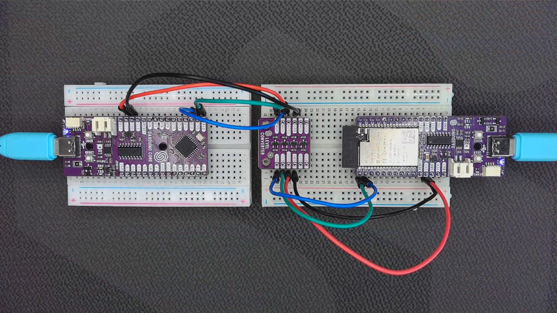
Bidirectional Logic Level Converter usage example
| Dasduino CORE (5V) | Logic Level Converter | Pin Name |
|---|---|---|
| VCC | HVCC | High Voltage Power |
| GND | GND | Ground |
| TXD | HV2 | High Voltage Pin for TXD |
| RXD | HV1 | High Voltage Pin for RXD |
| Dasduino CONNECTPLUS (3.3V) | Logic Level Converter | Pin Name |
|---|---|---|
| 3V3 | LVCC | Low Voltage Power |
| GND | GND | Ground |
| TXD | LV1 | Low Voltage Pin for TXD |
| RXD | LV2 | Low Voltage Pin for RXD |