LSM9DS1TR – How it works
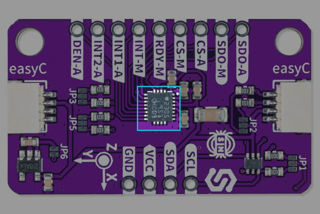
The Accelerometer & Gyroscope & Magnetometer LSM9DS1TR 9-DOF breakout is an integrated circuit by STMicroelectronics. It is an all-in-one package that combines a 3D digital linear acceleration sensor, a 3D digital angular rate sensor, and a 3D digital magnetic sensor, allowing linear acceleration, rotational motion, and magnetic field to be tracked in three dimensions.
Datasheet
For an in-depth look at technical specifications, refer to the official LSM9DS1TR 9-DOF Datasheet:
LSM9DS1TR 9-DOF Datasheet
Detailed technical documentation for the Accelerometer & Gyroscope & Magnetometer LSM9DS1TR 9-DOF
How the accelerometer works
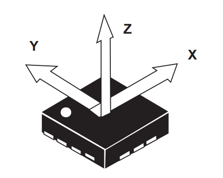
The accelerometer on this board works by detecting the movement of its mass, where its movement caused by external force input is then transformed into readable input that is transferred into data. It operates by containing a tiny proof mass (body of mass) attached to a spring within its casing. When acceleration occurs, the proof mass moves relative to the casing due to inertia, causing the spring to compress or stretch. This movement is detected by capacitive or piezoresistive sensors, which convert the mechanical displacement into electrical signals. These signals are then processed and amplified by onboard electronics to provide precise measurements of acceleration, supporting full-scale ranges from ±2 g to ±16 g.
How the gyroscope works
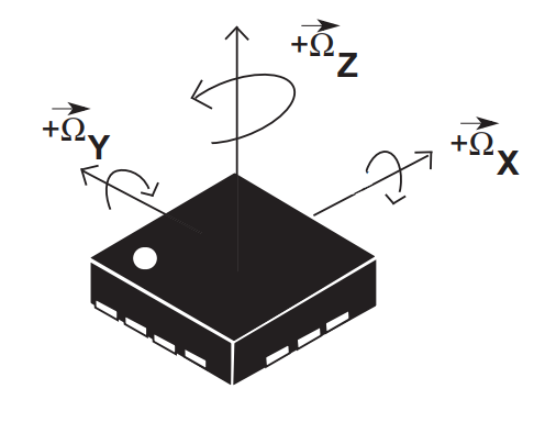
The gyroscope on this board works in a similar manner to the accelerometer, with the simple difference that it works by containing tiny vibrating structures that move due to the Coriolis force when rotation occurs. This movement is detected by capacitive or piezoresistive sensors, which convert the mechanical displacement into electrical signals. These signals are then processed and amplified by onboard electronics to provide precise measurements of the angular rate, supporting full-scale ranges from ±125 dps to ±2000 dps. The gyroscope's operation is based on MEMS technology, ensuring high precision and low power consumption, making it suitable for applications such as drone stabilization and robotics. The gyroscope's design allows for efficient data management and low-power modes, ensuring optimal performance without significant energy consumption.
How the magnetometer works
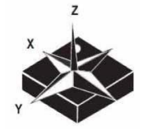
The magnetometer on this board operates by detecting changes in the magnetic field using Hall effect sensors or anisotropic magnetoresistive (AMR) sensors. These sensors convert the magnetic field variations into electrical signals, which are then processed and amplified by onboard electronics to provide precise measurements of the magnetic field strength and direction. The magnetometer supports full-scale ranges from ±4 gauss to ±16 gauss, allowing it to function as a digital compass and enabling applications such as navigation systems and orientation sensing. The magnetometer's operation is based on MEMS technology, ensuring high precision and low power consumption, making it suitable for applications like indoor navigation and augmented reality. The magnetometer's design allows for efficient data management and low-power modes, ensuring optimal performance without significant energy consumption.
I2C communication
The LSM9DS1TR uses the I2C protocol to communicate with a microcontroller, supporting both standard and fast modes (100 kHz and 400 kHz) for efficient data transmission. The sensor has multiple I2C addresses depending on the state of the SDO_A/G (SDO-A) and SDO_M pins, which determine the addresses for the accelerometer/gyroscope and magnetometer, respectively.
The typical I2C addresses are:
- Accelerometer and Gyroscope: 0x6A or 0x6B depending on the SDO_A/G pin state.
- Magnetometer: 0x1C or 0x1E depending on the SDO_M pin state.
These addresses can be configured by adjusting the logic levels on the SDO_A/G and SDO_M pins, allowing flexibility in I2C bus management. For multiple LSM9DS1 devices on the same I2C bus, an I2C multiplexer can be used to manage different addresses and prevent conflicts.
Measurement process
-
Power-up and Initialization
- The LSM9DS1 enters a low-power mode when powered on.
- On initialization, send a command to initialize the sensor. This typically involves setting the desired measurement ranges for the accelerometer, gyroscope, and magnetometer, as well as configuring any additional features like FIFO buffering or interrupt settings.
-
Taking a Measurement
- Send a command to start the measurement process.
- The sensor captures data for linear acceleration, angular rate, and magnetic field strength. The measurement process is typically continuous once started, with data being stored in the FIFO buffer if configured.
-
Data Retrieval
- Use I2C or SPI to read the latest data from the sensor. This involves sending a read command to the sensor's address and retrieving the stored data.
- The sensor outputs raw data for acceleration, angular velocity, and magnetic field strength, which may need to be converted into meaningful units (e.g., g for acceleration, dps for angular rate, gauss for magnetic field) using the sensitivity values provided in the datasheet.
-
Additional Steps
- If the FIFO buffer is used, manage its contents by reading data regularly to prevent overflow or use interrupts to signal when new data is available.
- Process the retrieved data to extract meaningful information such as orientation, motion patterns, magnetic field direction, or other desired metrics. This can involve combining data from all three sensors to achieve accurate navigation or gesture recognition capabilities.