Mcp23017 – How it works
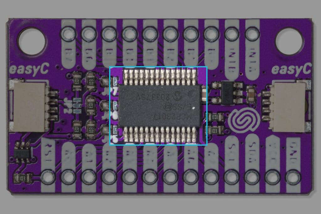
The I/O expander board works and communicates thanks to the MCP23017 chip by Microchip Technology
Datasheet
For an in-depth look at technical specifications, refer to the official MCP23017 Datasheet:
MCP23017 Datasheet
Detailed technical documentation for the MCP23017 chip
How it works
Along with the communication hardware, the chip we're using contains two 8-bit GPIO (general-purpose input/output) modules, providing a total of 16 inputs/outputs. For each of them, we can determine whether it is an input or an output. If a GPIO pin works as a digital input, its functionality can simply be described as that of a voltage comparator. Depending on the IC’s power supply, the controller determines which voltage range is considered low and which is considered high. When we use a GPIO as an input, we want to determine if a physical (analog) signal is above a certain voltage level and, based on that, assign the value “HIGH”; if it is below that level, we assign “LOW.” Often, the signals we want to read as “HIGH” or “LOW” are not constant, and their voltage can fluctuate. That is why this IC uses the so-called Schmitt trigger. This ensures a safety zone into which the measured signal can enter without the controller misinterpreting it.

If we have set a GPIO pin to work as a digital output, the situation is simpler. Through communication, we receive information on whether to set the pin as “LOW” or “HIGH.” If we receive “LOW,” the output is connected to ground; if we receive “HIGH,” the output is connected to the power supply. GPIO inputs have a built-in pull-up resistor, so we can simply add push buttons and switches without additional hardware.
This IC has another interesting feature – hardware interrupt. It can be programmed so that the breakout triggers an interrupt when there is a change on either GPIO module; accordingly, the board has two pins marked with INTA and INTB.