MCP47A1 – How it works
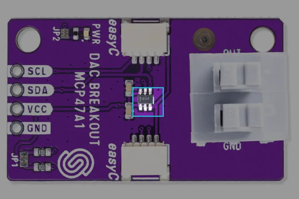
The MCP47A1 is an integrated circuit by [Microchip Technology]. When using our board, you are essentially communicating with the onboard MCP47A1 directly via I2C communication.
Datasheet
For an in-depth look at technical specifications, refer to the official MCP47A1 Datasheet:
MCP47A1 Datasheet
Detailed technical documentation for the MCP47A1 DAC
How it works
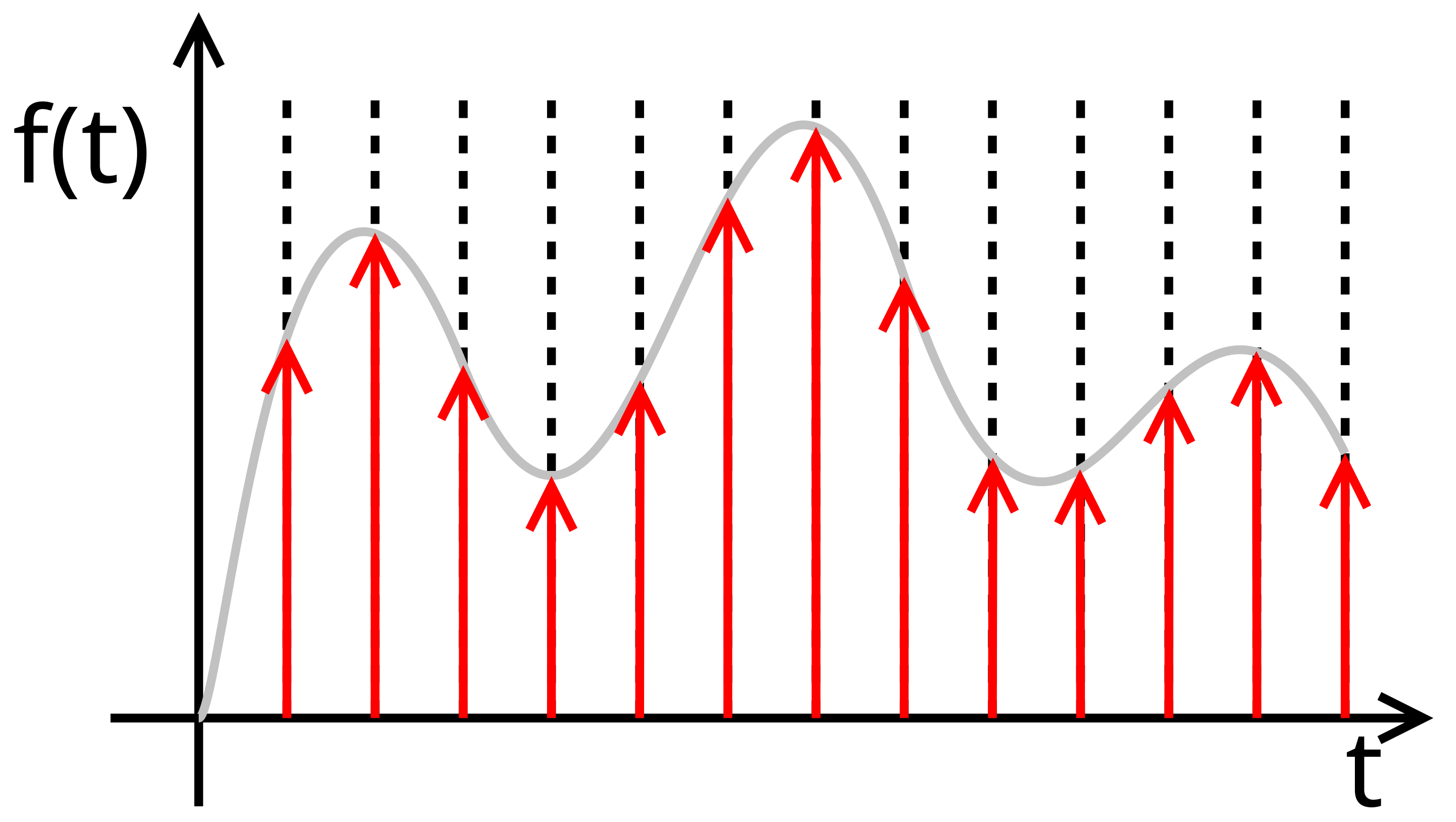
Digital to Analog Conversion (DAC) is the process of transforming digital signals, which consist of discrete binary values (0s and 1s), into continuous analog signals. This is necessary because most real-world applications, such as sound reproduction, video display, and industrial control systems, require smooth, continuous signals rather than discrete digital values.
The conversion process begins with a digital input, typically represented as a series of binary numbers. Each binary value corresponds to a specific voltage or current level. The DAC interprets these binary numbers and generates a corresponding analog voltage or current. However, since digital signals change in discrete steps, the initial analog output appears as a staircase-like waveform rather than a smooth signal. To make it truly continuous, the output is often passed through a low-pass filter, which removes high-frequency noise and smooths the transitions between steps.
I2C communication
The MCP47A1 uses the I2C protocol to communicate with a microcontroller. It operates with a fixed I2C address of 0x2E. Over I2C, we can give the MCP47A1 commands to change the converted output voltage, as well as have it output a waveform.