DVI Output
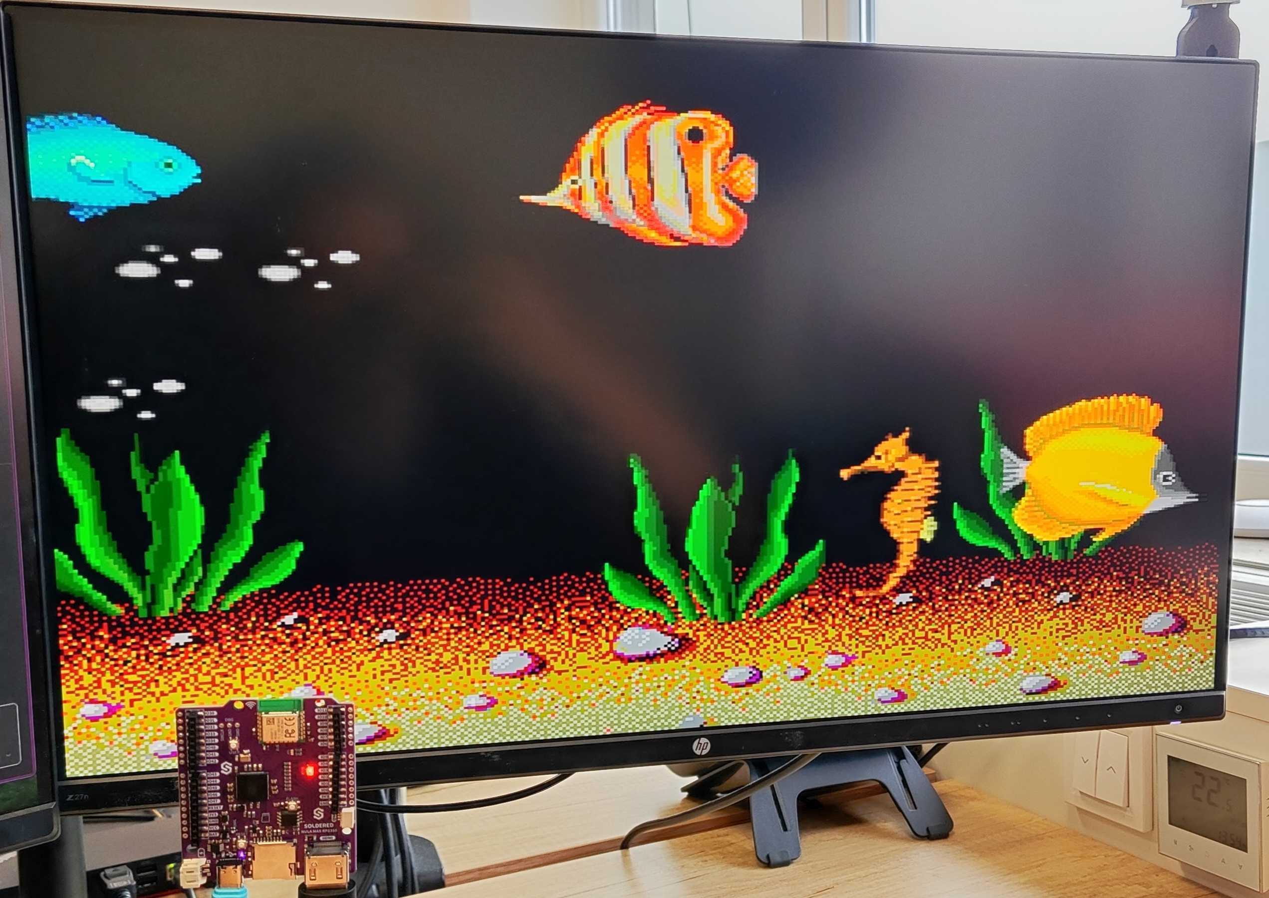
The Soldered NULA Max RP2350 board features built-in DVI output capability, enabling it to display images, graphics, and animations directly on any DVI-compatible display. This is achieved through the PicoDVI library, which uses the RP2350’s PIO (Programmable I/O) system to bit-bang a DVI/DVI signal entirely in software—no dedicated video hardware required. The implementation supports framebuffer-based rendering, allowing smooth animation and static image output in various color modes. Despite being a software-driven approach, PicoDVI efficiently leverages the RP2350’s dual-core performance and fast I/O to deliver surprisingly fluid DVI visuals, making the NULA Max ideal for compact embedded projects, UI displays, and creative graphics demos.
We have made a fork of the original PicoDVI library, which makes it and the examples plug-and-play with our NULA Max RP2350 board. The library can be found below:
PicoDVI - Soldered Electronics fork
A fork of the original PicoDVI library specifically tailored to work with the Soldered NULA Max RP2350 board
Download the library as a .zip file and then, in the Arduino IDE, go to Sketch->Include Library->Add .ZIP Library.
The library implements the Adafruit GFX library, which greatly simplifies the drawing process.
Supported resolutions and framerates
The PicoDVI library supports a range of resolutions and framerates for your specific needs; they are defined in the following table:
| Resolution | Framerate |
|---|---|
| 320x240 | 60fps |
| 400x240 | 30fps |
| 400x240 | 60fps |
| 640x480 | 30fps |
| 640x480 | 60fps |
| 800x480 | 30fps |
| 800x480 | 60fps |
| 640x240 | 60fps |
| 800x240 | 30fps |
| 800x240 | 60fps |
It is also possible to output color in 1-bit, 8-bit, and 16-bit modes.
Simple example
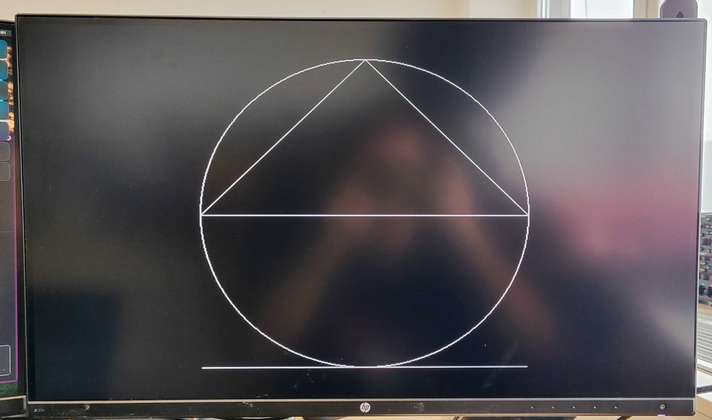
In the following example, we will draw a line, a circle, and a triangle on the screen in 800x480 resolution at 30fps.
// Simple 1-bit Adafruit_GFX-compatible framebuffer for PicoDVI.

#include <PicoDVI.h>
#include <Adafruit_NeoPixel.h>

// Here's how a 640x480 1-bit (black, white) framebuffer is declared.
// Second argument ('false' here) means NO double-buffering; all drawing
// operations are shown as they occur. Third argument is a hardware
// configuration — examples are written for Soldered NULA RP2350
DVIGFX1 display(DVI_RES_800x480p30, false, soldered_nula_rp2350_dvi_cfg);

// Configure WSLED parameters
Adafruit_NeoPixel pixels(1, 26); // WSLED object

void setup() { // Runs once on startup
  // Initialize the onboard NeoPixel RGB, used for debugging
  pixels.begin();

  // Try to initialize the framebuffer for the video output
  if (!display.begin()) {
    // Blink LED red infinitely - something's wrong
    while (true)
    {
        pixels.setPixelColor(0, pixels.Color(0x20, 0, 0)); // Set the color to red
        pixels.show();
        delay(400);
        pixels.clear();
        pixels.show();
        delay(400);
    }
  }
  // Draw a circle with the center at (400,240), a radius of 200px, and the color white (1)
  display.drawCircle(400, 240, 200, 1);

  // Draw a triangle with vertices at (200,240), (400,40), (600,240) and the color white (1)
  display.drawTriangle(200, 240, 400, 40, 600, 240, 1);

  // Draw a line from (200,440) to (600,440) with the color white (1)
  display.drawLine(200, 440, 600, 440, 1);
}

void loop() {

}
display.begin()
Initializes the framebuffer for writing to the display
Returns value: Boolean value, true if the buffer initialization was successful, false if not
display.drawCircle()
Draws a circle outline on the display.
Returns value: none
Function parameters:
| Type | Name | Description |
|---|---|---|
int | x | The x-coordinate of the circle center. |
int | y | The y-coordinate of the circle center. |
int | radius | The radius of the circle. |
uint8_t | color | The color of the circle outline. |
display.drawTriangle()
Draws a triangle outline on the display.
Returns value: none
Function parameters:
| Type | Name | Description |
|---|---|---|
int | x0 | The x-coordinate of the first vertex. |
int | y0 | The y-coordinate of the first vertex. |
int | x1 | The x-coordinate of the second vertex. |
int | y1 | The y-coordinate of the second vertex. |
int | x2 | The x-coordinate of the third vertex. |
int | y2 | The y-coordinate of the third vertex. |
uint8_t | color | The color of the triangle outline. |
display.drawLine()
Draws a straight line between two points on the display.
Returns value: none
Function parameters:
| Type | Name | Description |
|---|---|---|
int | x0 | The x-coordinate of the starting point. |
int | y0 | The y-coordinate of the starting point. |
int | x1 | The x-coordinate of the ending point. |
int | y1 | The y-coordinate of the ending point. |
uint8_t | color | The color of the line. |
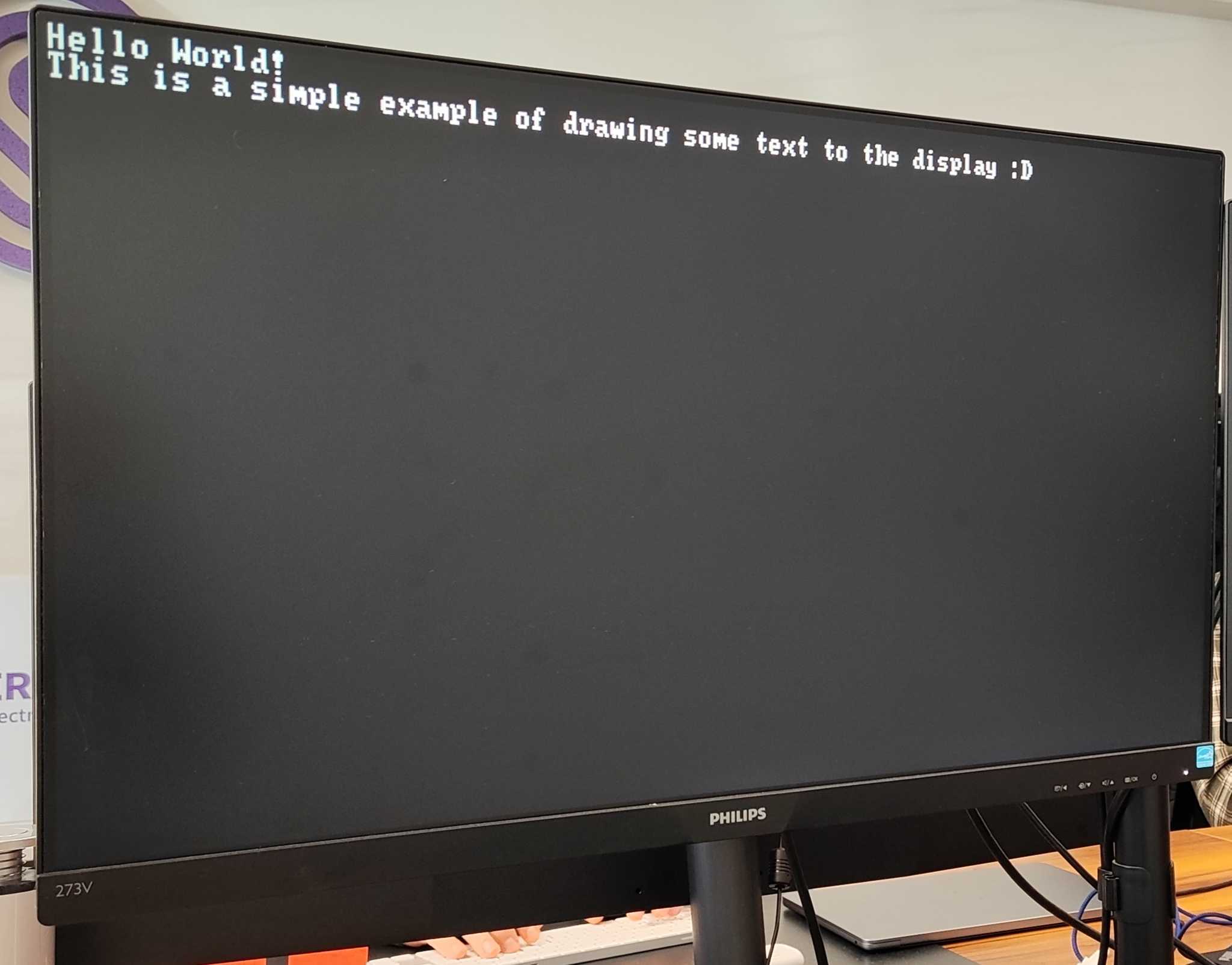
Text Example
The following example shows how to draw text on the screen.
// 1-bit (black, white) text mode for PicoDVI.

#include <PicoDVI.h>
#include <Adafruit_NeoPixel.h>
// Here's how an 80x30 character display is declared. The first argument,
// resolution, is the full display pixel count; character cells are 8x8 pixels,
// yielding the 80x30 result. The 640x240 resolution uses "tall" pixels, which is
// very reminiscent of the classic IBM VGA mode. The second argument is a hardware
// configuration — examples are written for Soldered NULA RP2350.
DVItext1 display(DVI_RES_640x240p60, soldered_nula_rp2350_dvi_cfg);

// Configure WSLED parameters
Adafruit_NeoPixel pixels(1, 26); // WSLED object

void setup() { // Runs once on startup
  // Initialize the onboard NeoPixel RGB, used for debugging
  pixels.begin();

  // Try to initialize the display framebuffer
  if (!display.begin()) {
    // Blink LED red infinitely - something's wrong
    while (true)
    {
        pixels.setPixelColor(0, pixels.Color(0x20, 0, 0)); // Set the color to red
        pixels.show();
        delay(400);
        pixels.clear();
        pixels.show();
        delay(400);
    }
  }

  // Write to the first line and then move to the next line
  display.println("Hello World!");
  // Continue writing on the next line
  display.print("This is a simple example of drawing some text to the display :D");
}

void loop() {
}
display.print(const char* _c)
Prints text at the previously set cursor position. This is the standard Arduino print function used in many native Arduino objects and libraries.
Returns value: size_t, number of bytes printed.
Function parameters:
| Type | Name | Description |
|---|---|---|
const char * | _c | The C-style string to print on the display. |
Animation example
The following is an animation showing the speed at which the display can refresh.
Code is available at the link below:
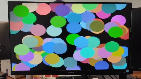
Double buffer example
An example showing multi-colored balls jumping on the screen