Relay – How it works
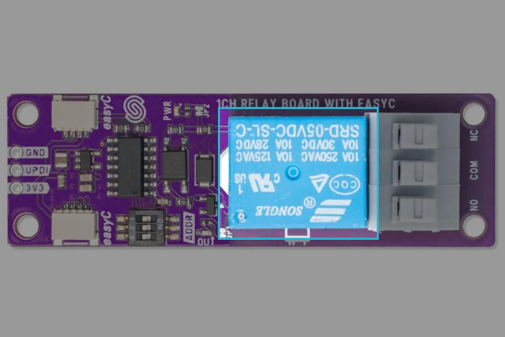
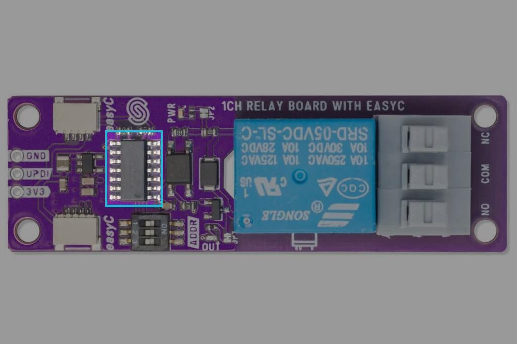
This is a circuit board with integated SRD-05VDC-SL-C relay by SONGLE. It comes in both single channel (1 relay) and multi channel (2 and 4 relays) version. For Qwiic, currenty 1 and 2 channel versions are available. When using an Qwiic version you are essentially communicating with an onboard ATTINY404 MCU via I2C communication.
Datasheet
For an in-depth look at technical specifications, refer to the official SRD-05VDC-SL-C Datasheet:
SRD-05VDC-SL-C Datasheet
Detailed technical documentation for the SRD-05VDC-SL-C Datasheet relay
How the board works
Relay board is an electronic switch that allows a low-power signal to controll a higher power circuit. It consists of an electormagnet (coil), a movable armature, and one or more sets of electircal contacts. When current flows through the coil, it creates a magnetic field. The magnetic field pulls the armature, causing the contacts to switch states (either opening or closing the circuit). When the current stops, the magnetic field dissapears, and a spring returns the contacts in their default position.

Output LEDs
To help visualize if board is operational, each relay on board is accompanied by an LED indicator . These LEDs light up when the corresponding relay is activated, providing a real-time indication of which coil is currently energized. To activate the LED lights, jumpers must be bridged!
I2C communication - Qwiic
Qwiic versions of the product use onboard ATTINY404 MCU to implement I2C communication. Breakout board perates with a default I2C address of 0x30 but can be changed with onboard switches, to cange breakout board's address, check the When detected, Address selection.ATTINY404 recives data from sensor and passes it to the main MCU using I2C data line. To check in detail how to ATTINY404 is preprogrammed, check firmware github page.