Rs 485 - Arduino (Example)
In this example, two Dasduino ConnectPlus boards are connected using the RS-485 protocol to enable serial communication. The objective is for one Dasduino (Sender) to transmit commands ("ON" or "OFF") via RS-485 to the second Dasduino (Receiver), which processes these commands to control an LED (the LED is protected with a 330Ω resistor).
Sender Code:
#include <HardwareSerial.h>

HardwareSerial rs485Serial(1); // Use UART1

const String ON_COMMAND = "ON";
const String OFF_COMMAND = "OFF";

void setup() {
  Serial.begin(115200); // Debugging via Serial Monitor
  rs485Serial.begin(115200, SERIAL_8N1, 14, 13); // Initialize RS-485 communication (RX=14, TX=13)
  pinMode(12, OUTPUT); // DE pin for enabling driver
}

void loop() {
  digitalWrite(12, HIGH); // Enable driver for transmission
  rs485Serial.println(ON_COMMAND); // Send "ON" command
  Serial.println("Sent: " + ON_COMMAND); // Debugging: Confirm data sent
  delay(2000);

  rs485Serial.println(OFF_COMMAND); // Send "OFF" command
  Serial.println("Sent: " + OFF_COMMAND); // Debugging: Confirm data sent
  delay(2000);
}
Receiver Code:
#include <HardwareSerial.h>

HardwareSerial rs485Serial(2); // Use UART2
#define LED_PIN 33              // Define GPIO pin for LED

const String ON_COMMAND = "ON";
const String OFF_COMMAND = "OFF";

void setup() {
  rs485Serial.begin(115200, SERIAL_8N1, 26, 27); // Initialize RS-485 communication (RX=26, TX=27)
  Serial.begin(115200);                           // Debugging via Serial Monitor
  pinMode(LED_PIN, OUTPUT);                       // Set LED pin as output
  pinMode(2, OUTPUT);                            // NRE pin for enabling receiver
}

void loop() {
  digitalWrite(2, LOW); // Enable receiver for receiving data

  if (rs485Serial.available()) {
    String command = rs485Serial.readStringUntil('\n'); // Read incoming command
    command.trim();                                     // Remove extra whitespace or newline characters
    Serial.println("Received: " + command);             // Debugging: Print trimmed command

    if (command == ON_COMMAND) {
      digitalWrite(LED_PIN, HIGH); // Turn on LED
      Serial.println("LED turned ON");
    } else if (command == OFF_COMMAND) {
      digitalWrite(LED_PIN, LOW); // Turn off LED
      Serial.println("LED turned OFF");
    } else {
      Serial.println("Command is neither ON nor OFF");
    }
  }
}
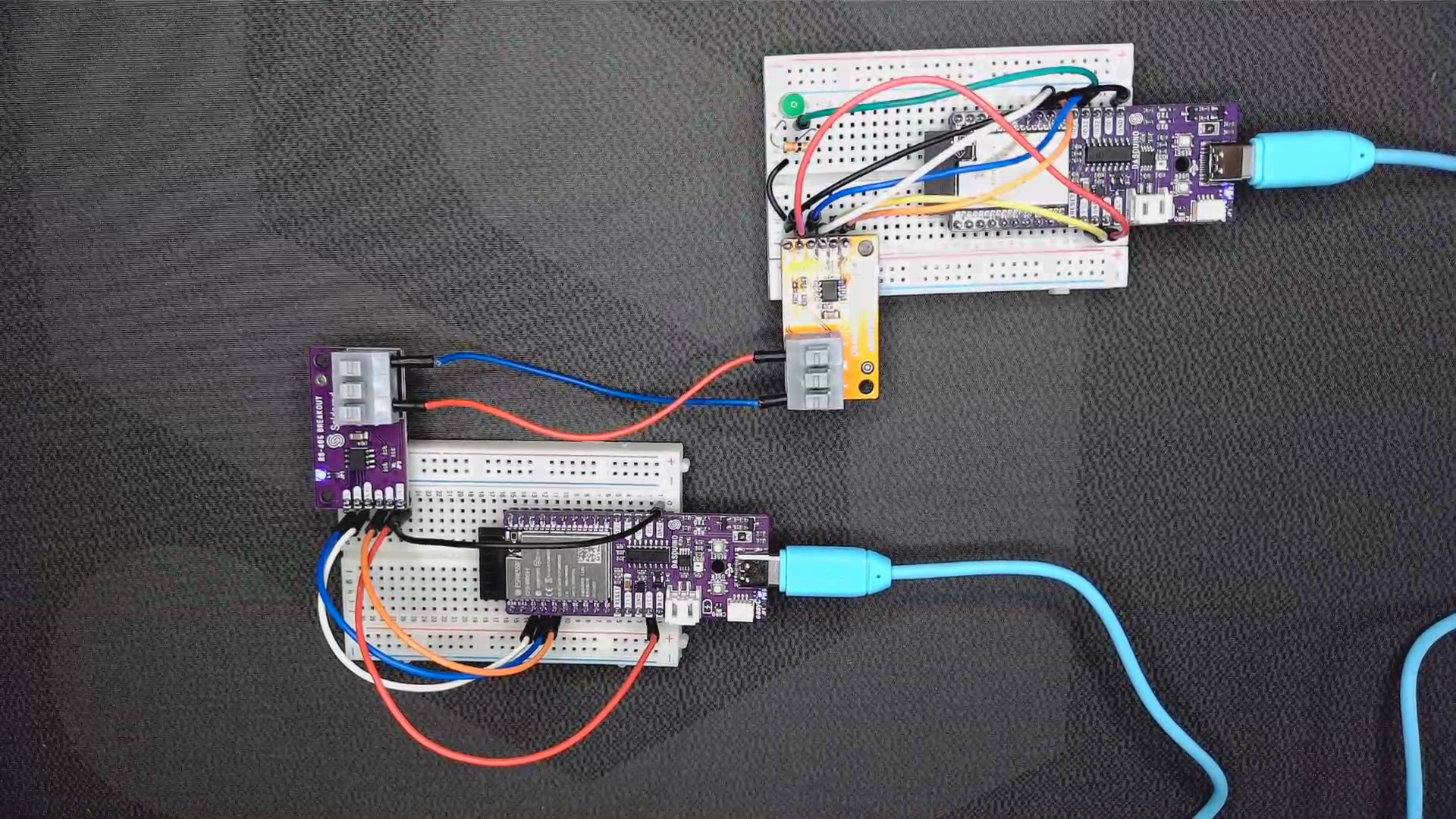
Breadboard connection for given example
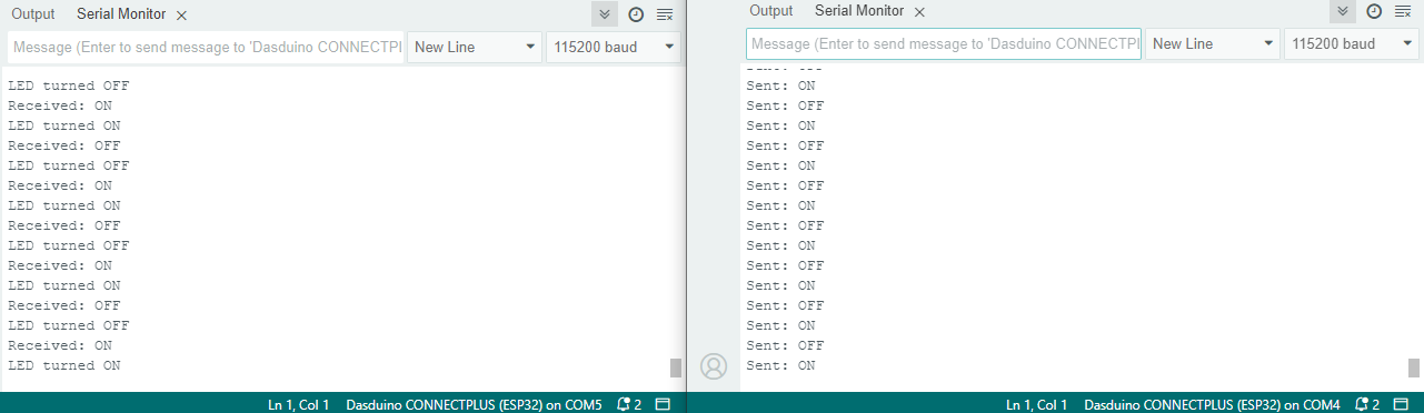
Side by side serial monitor outputs
ℹ️
Why you should use a 330Ω resistor on the LED A 330Ω resistor is recommended to limit the current flowing through the LED, preventing it from burning out. Without the resistor, the LED may draw excessive current, potentially damaging both the LED and the GPIO pin of your Dasduino board.