Rs 485 – How it works
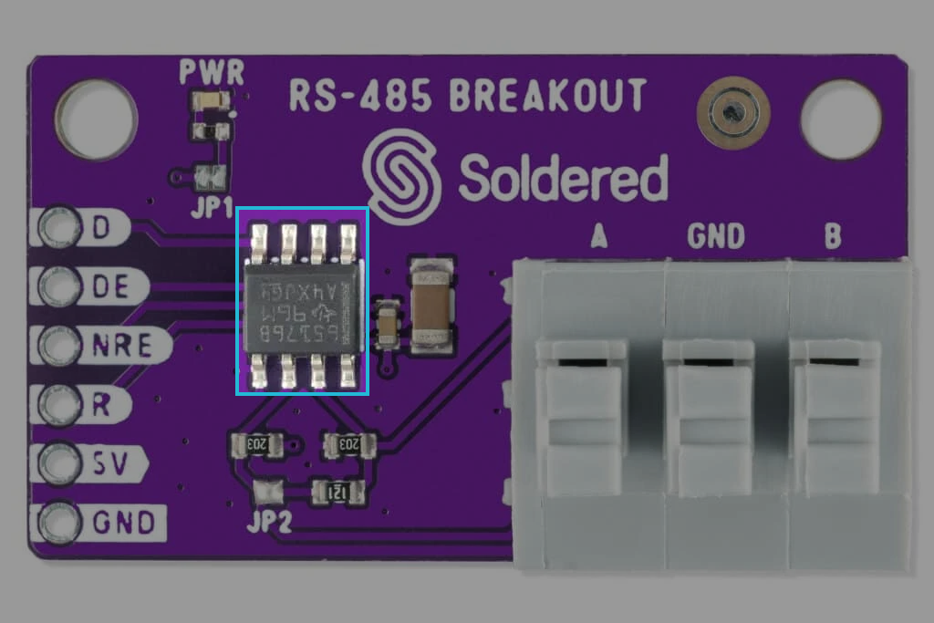
The RS-485 Transceiver Breakout Board by Soldered enables seamless communication between devices using the RS-485 protocol. It leverages the SN65176BDR integrated circuit, which provides robust differential signal transmission and reception, ensuring reliable communication over long distances (up to 1200 meters) and in noisy environments. This makes it ideal for industrial systems, motor control, and other applications requiring RS-485 connectivity.
How it works
The RS-485 Transceiver Breakout Board acts as a bridge between your microcontroller and the RS-485 bus. It converts TTL logic levels (0V to 5V) from your microcontroller into the differential signals required for RS-485 communication, and vice versa. This is achieved using the SN65176BDR chip, which handles signal transmission and reception while ensuring robustness in high-noise environments.
Main Points:
- Differential Signal Transmission:
- RS-485 uses two data lines (A and B) to transmit data as a differential signal, making it highly resistant to noise.
- Bidirectional Communication:
- The board supports bidirectional data transfer by toggling the DE (Driver Enable) and NRE (Receiver Enable) pins.
- Termination Resistor:
- A built-in jumper (JP2) allows you to enable or disable a 120Ω termination resistor for proper signal termination at the ends of the RS-485 bus.
The SN65176BDR chip includes built-in ESD protection, ensuring reliable operation even in harsh environments.
Enable and Disable
The SN65176BDR operates as long as a stable 5V supply is provided. When unpowered, it can safely remain connected to active RS-485 devices without causing damage, thanks to its internal safeguards.
How to Connect It?
-
Connect Power:
- Attach the 5V pin to your power source (4.75V - 5.25V range).
- Connect the GND pin to the ground of both your microcontroller and RS-485 bus.
-
Wiring the Signals:
- Connect the D pin to the TTL data output of your microcontroller.
- Use the DE pin to enable the driver (set HIGH when transmitting).
- Use the NRE pin to enable the receiver (set LOW when receiving).
- Connect the A (Non-Inverting) and B (Inverting) pins to the RS-485 bus lines.
- The R pin outputs received TTL data from the RS-485 bus back to your microcontroller.
-
Termination Resistor Configuration:
- If this breakout board is at one end of the RS-485 bus, close jumper JP2 to enable the onboard 120Ω termination resistor.
- If it’s not at an end point, leave JP2 open.
This breakout board is ideal for connecting modern microcontrollers to industrial systems or creating multi-node communication networks using RS-485.