Slider Potentiometer - How it works
The Slider Potentiometer Breakout is a versatile module designed for manual resistance adjustment in various applications, such as audio equipment, robotics, and other control systems. It provides two independent analog outputs for seamless integration into your projects. When using the Qwiic version, you are essentially communicating with an onboard ATTINY404 MCU via I2C communication.
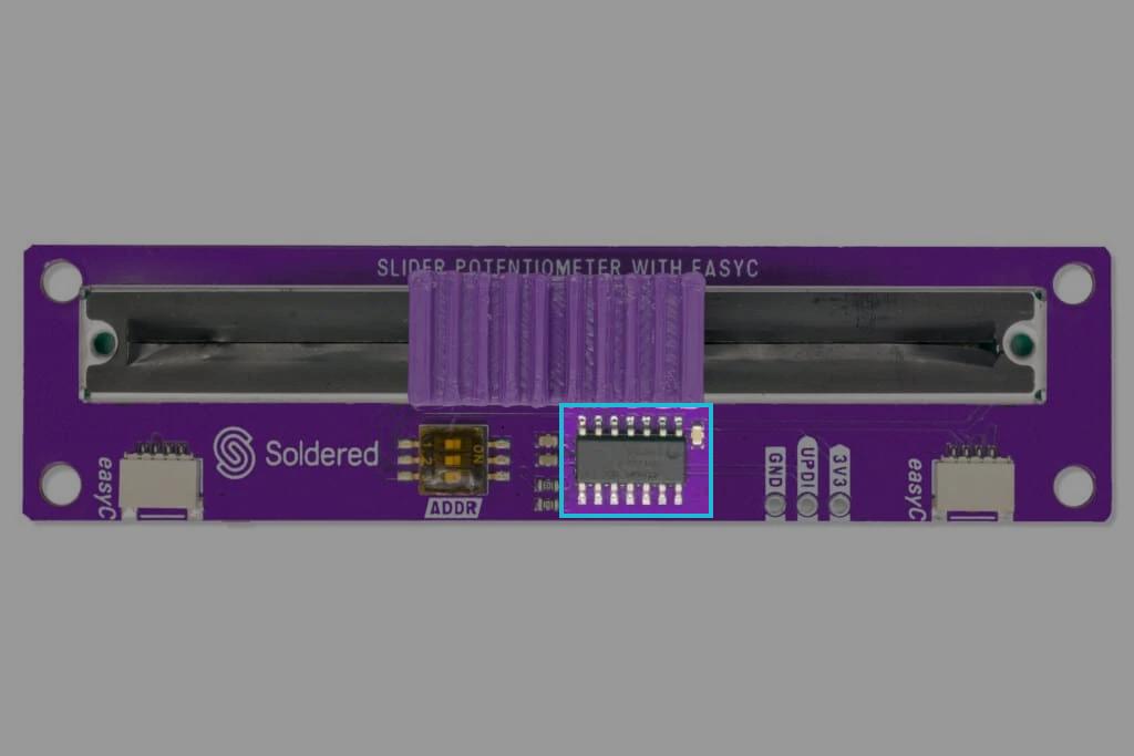
I2C communication - Qwiic
Qwiic versions of the product use the onboard ATTINY404 MCU to implement I2C communication. The breakout board operates with a default I2C address of 0x30 but can be changed with onboard switches. To change the breakout board's address, check the Address selection.
When detected, ATTINY404 receives data from the sensor and passes it to the main MCU using the I2C data line. To learn in detail how the ATTINY404 is preprogrammed, check the firmware GitHub page.
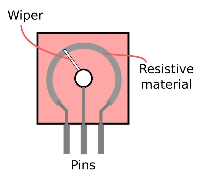
How the potentiometer works
The Slider Potentiometer is a passive component that adjusts resistance based on the position of its slider (wiper). It features two sets of pins (A and B) for dual analog output functionality. Each side can operate independently, providing flexibility for different configurations.
Internally, the potentiometer acts as a variable resistor, dividing voltage across its terminals. The position of the slider determines the output voltage on the wiper pin (OUTA or OUTB), enabling precise control in your circuit.
Measurement process
The operation of the Slider Potentiometer is straightforward:
-
Power connection
- Connect VCCA and/or VCCB to a power source (typically 5V).
- Ensure GND is connected to the common ground of your circuit.
-
Adjusting resistance
- Move the slider to adjust the resistance and voltage output on OUTA and/or OUTB.
-
Reading output
- Measure the analog voltage from OUTA or OUTB using an ADC pin on your microcontroller.