Microsd Reader – How it works
The SD card reader's communication is handled by the TXB0104 chip from Texas Instruments.
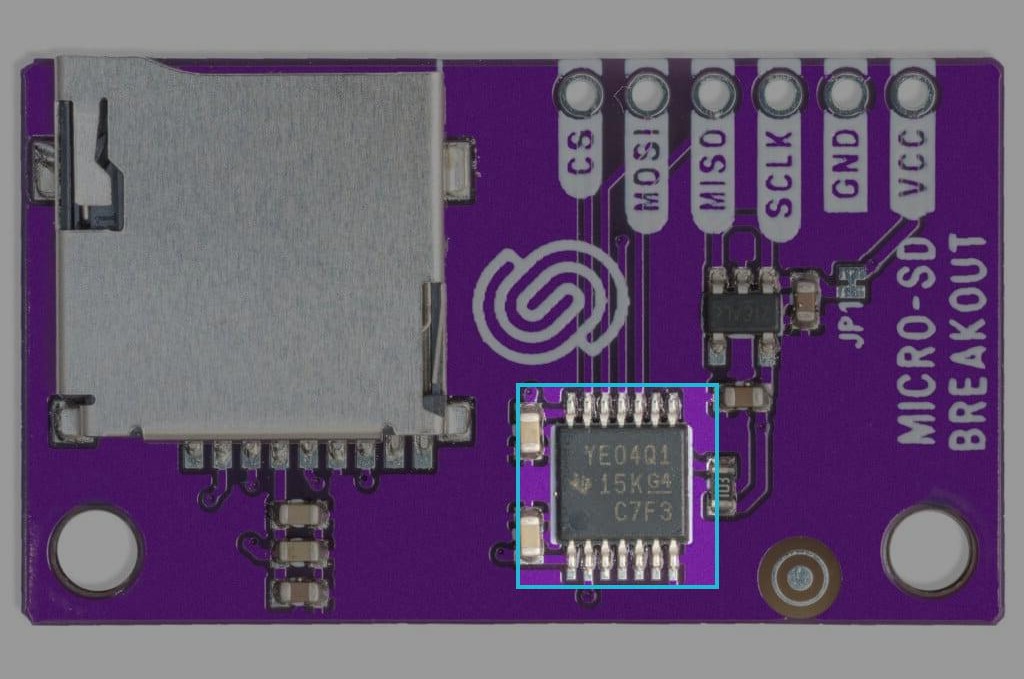
TXB0104 chip on board
Datasheet
For an in-depth look at the technical specifications, refer to the official TXB0104 Datasheet:
TXB0104 Datasheet
Detailed technical documentation for the TXB0104 chip
How an SD Card reader works
An SD card reader facilitates communication between an SD card and a host device by establishing electrical connections and enabling data transfer through standard protocols. Here’s a breakdown of its operation at the electrical level:
Electrical interface and pin configuration
The micro SD card's SPI interface is implemented using the standard 8-pin micro SD card pinout, with pins corresponding to SPI signals. Here's how the micro SD card pinout relates to the SPI signals:
| Pin | Pin Name | Description |
|---|---|---|
| 1 | RSV | Reserved (Not in use) |
| 2 | CS | Chip selection for SPI |
| 3 | DI | Data input |
| 4 | VDD | Power supply |
| 5 | SCLK | Serial clock for communication |
| 6 | VSS | Ground |
| 7 | DAT0 | Data output |
| 8 | RSV | Reserved (Not in use) |
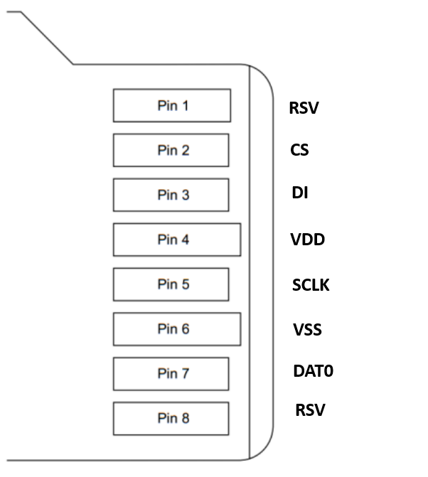
Pinout of an SD card
Power-on & Initialization
Once inserted, the SD card reader:
- Applies power (3.3V) to the SD card via the VDD pin.
- Performs a voltage check to confirm that the SD card operates within specifications.
- Activates the pull-up resistors to stabilize signals.
- Initiates the SD protocol.
Read operations
- The host sends a read command via the DI pin.
- The SD card locates the requested data and transmits it via the DAT0 pin.
- Synchronization is ensured by the serial clock.
Write operations
- The host sends a write command via the DI pin along with data blocks.
- The SD card writes the data to NAND flash memory while sending status responses.