Assembly guide
On this page, we will guide step by step on how to assemble this kit.
Step 1: Solder the resistors to the PCB.
Solder the 330 Ohm resistors to the PCB on pins marked R1 to R6. their orientation doesn't matter.
Find the resistors with markings as shown below:
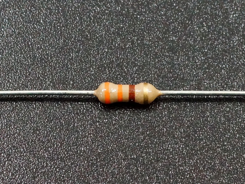
Markings for the 330 Ohm resistor
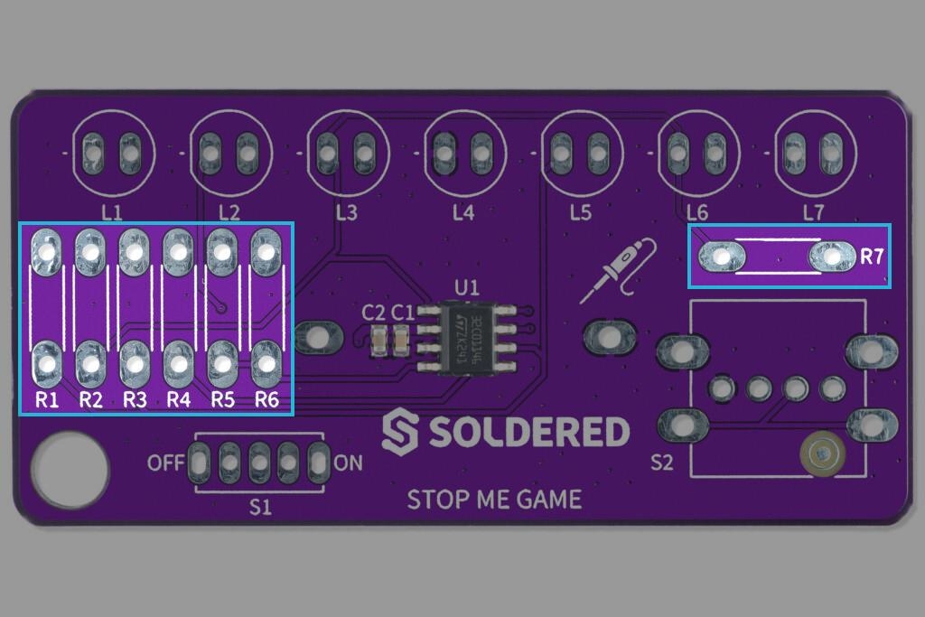
Highlighted pins for resistors R1 to R7
Step 2: Solder the switch
Solder the switch on pins marked S1, orientation doesn't matter.
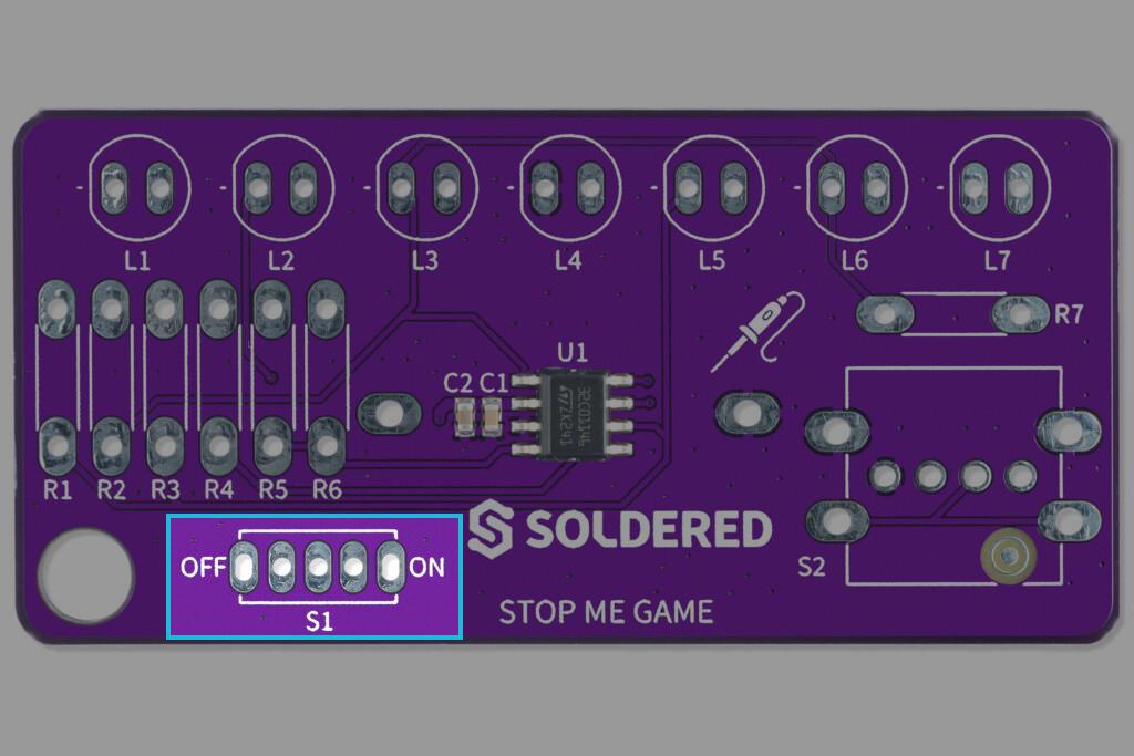
Highlighted pins for switch
Step 3: Solder the LEDs
Solder the LEDs on pins marked L1 to L7. Keep in mind that the LED's cathode (-) is on the left pin, and anode (+) is on the right side!
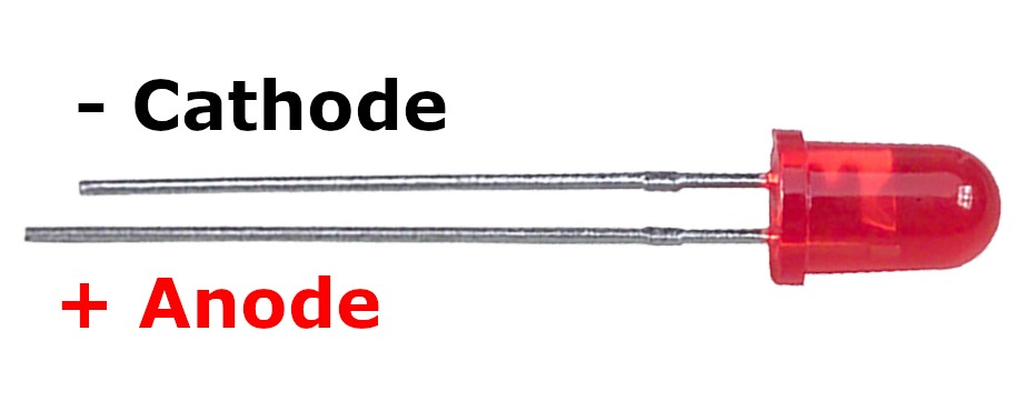
Marked pins on LED
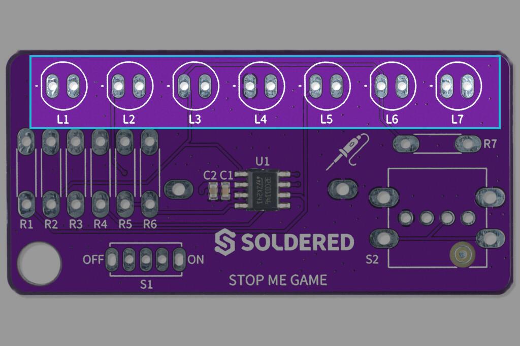
Highlighted pins for LEDs
Step 4: Solder the pushbutton
Solder the pushbutton on pins marked S2, orientation doesn't matter.
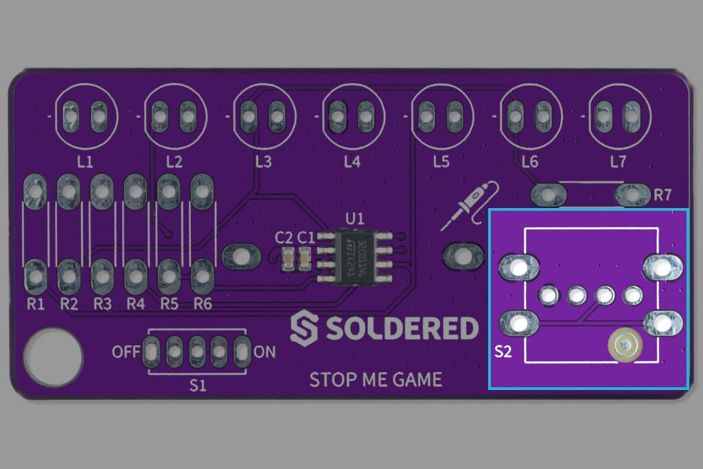
Highlighted pins for pushbutton
Step 5: Solder the CR2032 battery holder
Rotate the pcb on its back side up and align the holder with drawn topology on pins marked BAT.
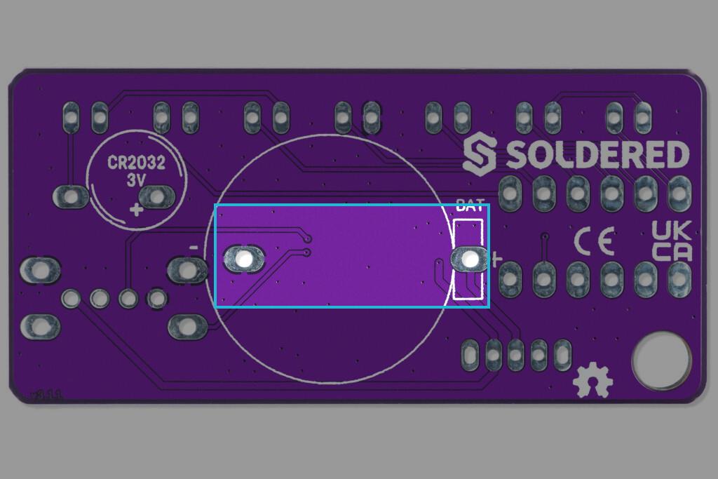
Highlighted pins for pushbutton