0.1 Breadboard Fundamentals
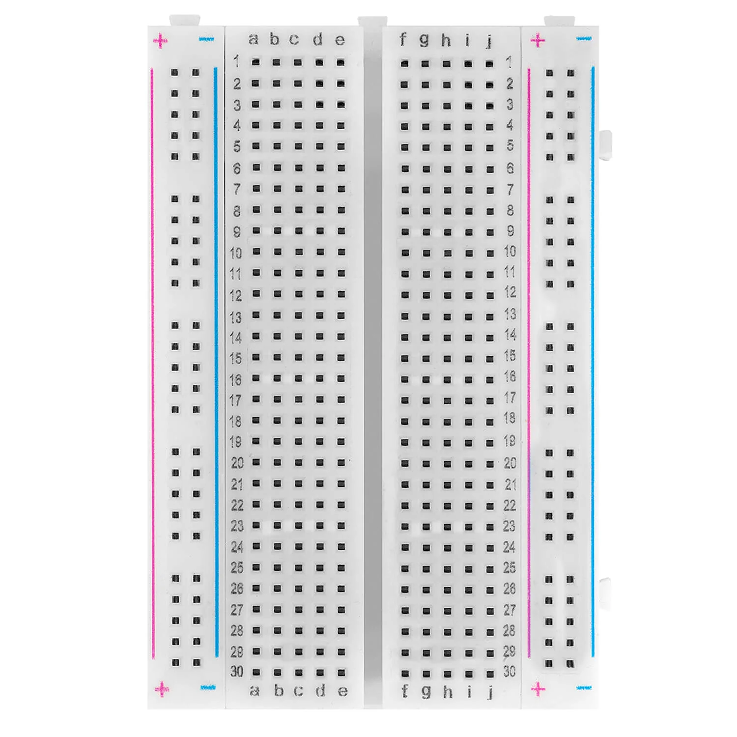
A breadboard is the board you build a circuit on without soldering anything. Components and wires push into its holes, and the connections inside do the rest, so a circuit takes a minute to build and a minute to take apart again.
In this documentation you will learn:
- What a breadboard is and why it is used
- How rows and columns inside a breadboard are connected
- How to place components and wires correctly
What is a breadboard?
A breadboard is a reusable platform for building electronic circuits. Instead of soldering components together permanently, you push wires, resistors, sensors and microcontroller pins into its holes. Inside the breadboard are metal clips that electrically connect certain holes together.
This allows you to:
- Quickly change connections
- Fix mistakes easily
- Reuse components many times
Breadboard layout
A breadboard looks confusing at first, but the layout is simple. It has two areas:
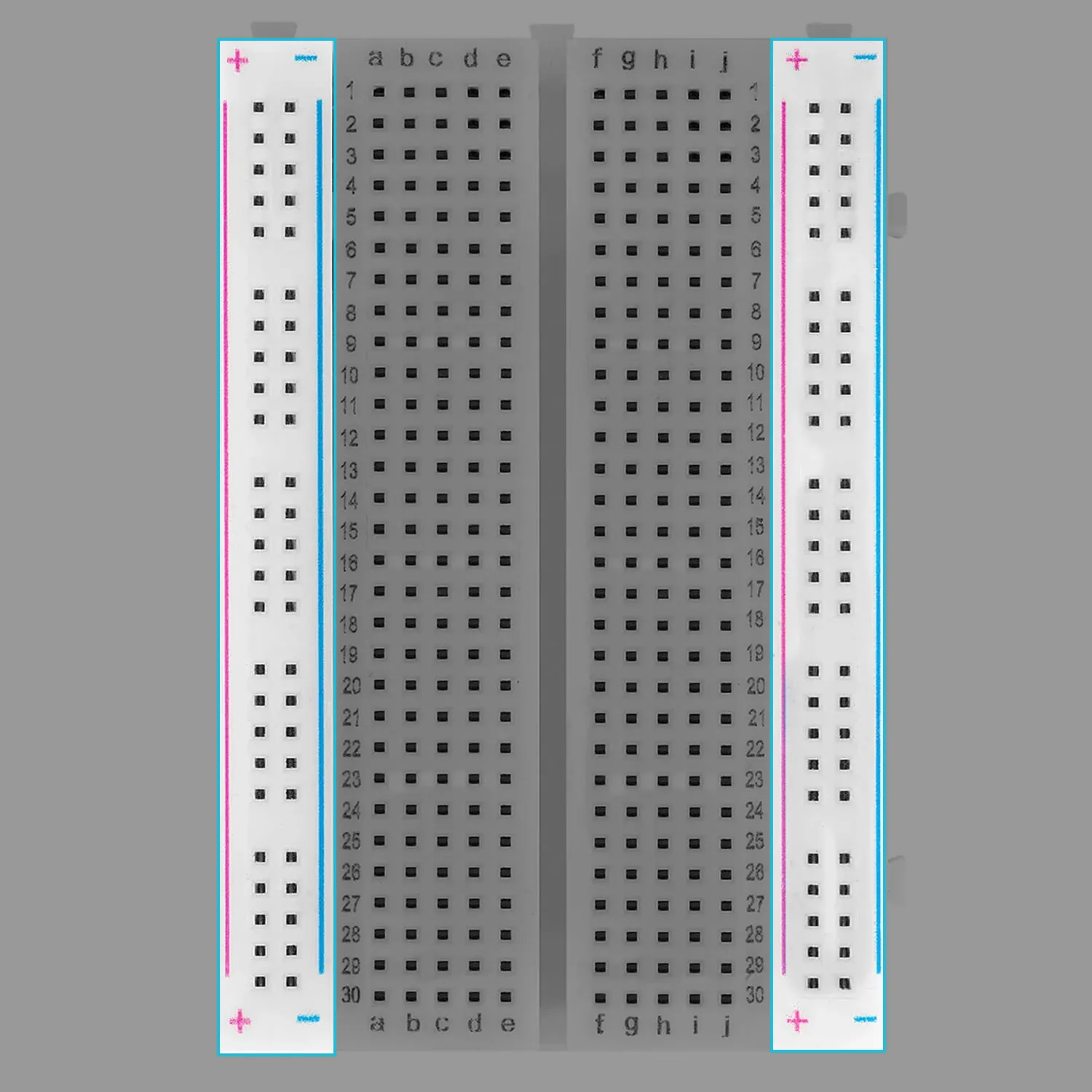
1. Power rails
The long rows on the left and right sides of the breadboard are called power rails. They are usually marked with a + (red) and a - (blue) line.
- All holes in a single power rail column are electrically connected
- They are typically used for VCC (3.3V or 5V) and GND
2. Terminal strips
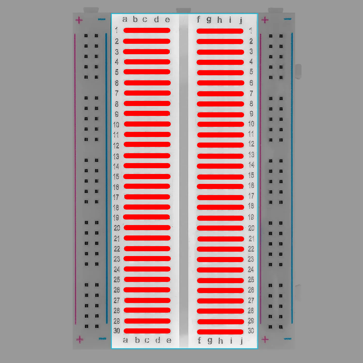
The centre of the breadboard is where most components go. It is divided by the middle gap, and that gap matters.
- Each row of 5 holes is electrically connected
- A row on one side of the gap is not connected to the row facing it on the other side
How connections work
One thing to keep in mind before you start:
Example of a correct connection
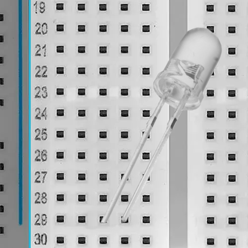
To correctly use a breadboard, each pin of a component must be placed in a different row so that there are no electrical shorts.
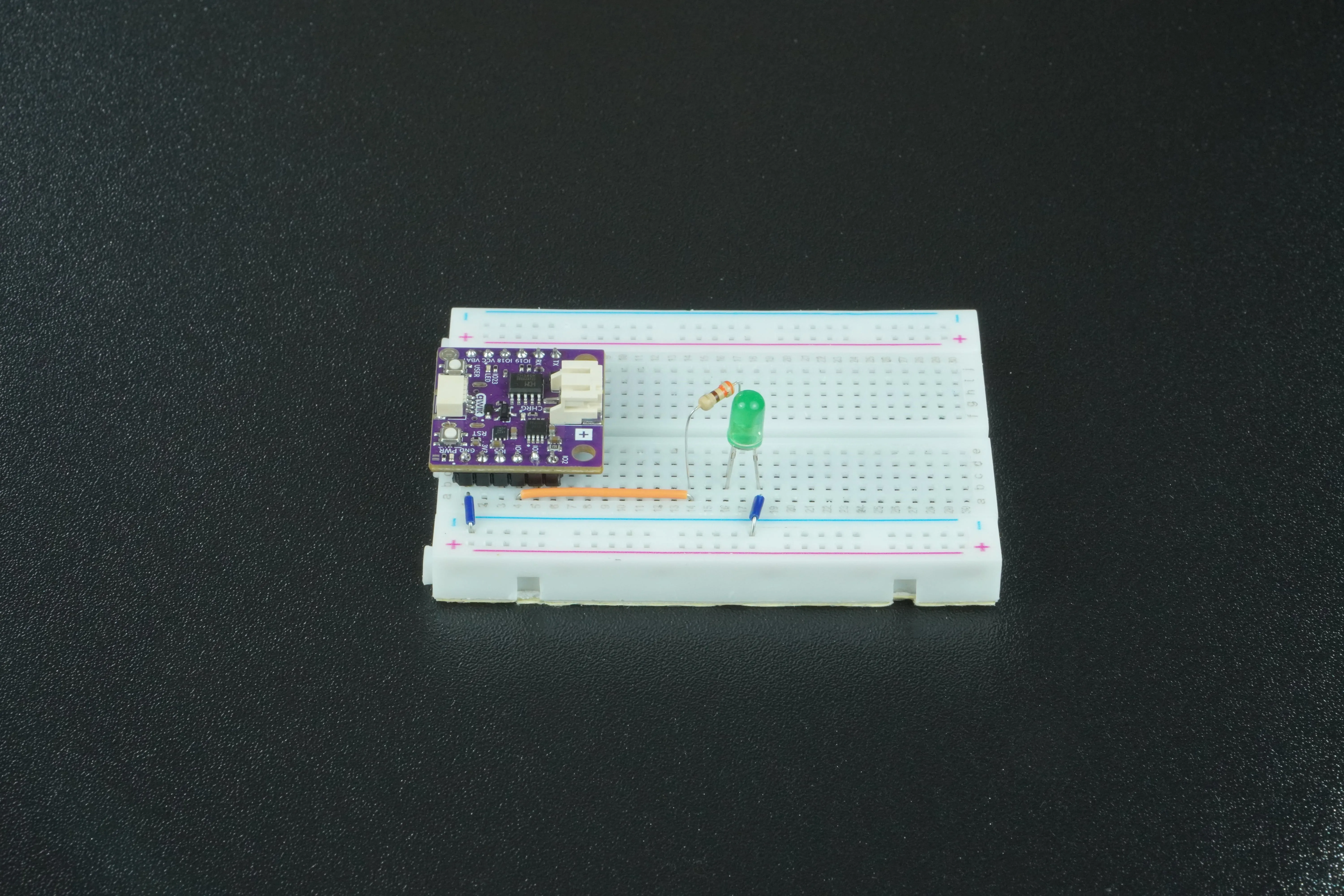
Here the LED has its two legs in different rows of the breadboard. One row goes to power through a resistor, in this example a GPIO pin on the NULA MINI, and the other goes to ground. Current then has to pass through the LED, which lights it safely.