About the Inventor kit
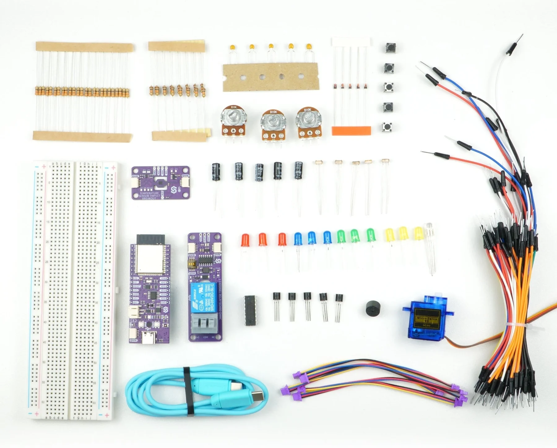
The Inventor kit is built around the NULA DeepSleep ESP32-S3.
One thing makes it different: you measure things. In most kits you wire a circuit up and a datasheet tells you what it does. Here the board measures your circuit and prints what it really does.
Task 13 reads the voltage across an LED's series resistor and works out that LED's forward voltage and current. Task 19 watches a capacitor charge and prints the time constant it measured beside the one the formula predicts. Task 24 finds the two pulse widths your servo really stops at, which are not the ones in the example file.
Every number these tasks print comes from your parts, not from a datasheet.
Which product is this documentation for?
Inventor Kit
333372
What is in the box
| Component | Quantity | Notes |
|---|---|---|
| NULA DeepSleep ESP32-S3 | 1 | Male headers fitted. ESP32-S3, CH340, PCF85063A RTC, WS2812B, Qwiic |
| Large breadboard | 1 | |
| Jumper wire set | 1 | |
| TMP117 temperature sensor | 1 | Qwiic, with the ALR pad broken out |
| 1-channel relay | 1 | Qwiic |
| Qwiic cable, 10 cm | 5 | |
| SN74HC595N shift register | 1 | DIP-16 |
| SG90 servo | 1 | Powered from VCC, never 3V3 |
| Buzzer QMB-09B-03 | 1 | Passive, so it needs an alternating signal |
| 5 mm LED | 13 | Three each of red, yellow, green and blue, plus one RGB |
| 10 kΩ potentiometer | 3 | |
| Small THT pushbutton | 5 | |
| 10 kΩ photoresistor | 5 | |
| NPN transistor, TO-92 | 5 | |
| 1N4148 diode | 5 | The band is the cathode |
| 330 Ω resistor | 25 | One in series with every LED |
| 10 kΩ resistor | 15 | |
| 100 nF capacitor | 5 | No polarity, either way round |
| 10 µF 25 V electrolytic capacitor | 5 | Polarised, stripe to GND |
| USB-C cable | 1 | Programming and power. A data cable, not a charge-only one |
The next page goes through each part: what it is, how to recognise it, and what to watch for when you push it in.
There is no meter either. The board measures its own circuits instead, and that is the idea the manual is built on.