The components
Every part in the box, what it does, and what to watch for when you push it in. Where a part has its own documentation, it is linked.
This page is for looking things up. You do not need to read it before starting.
The board and the breadboard
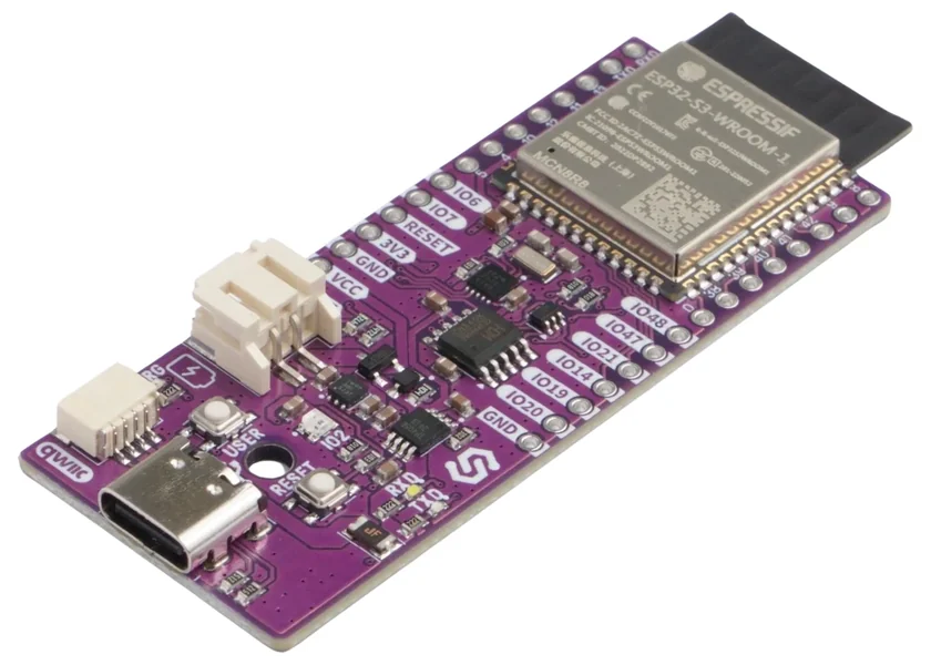
NULA DeepSleep ESP32-S3
The board that runs everything. An ESP32-S3 with Wi-Fi and Bluetooth, a USB-C port for programming and power, a Qwiic socket, an RGB LED and a real-time clock. Male headers are fitted, so it pushes straight into the breadboard.
Deep-sleep current is around 7 µA with the onboard LED jumper opened, which is why this board is the one in the kit.
NULA DeepSleep ESP32-S3
Pinout, hardware details, and how the board is put together.
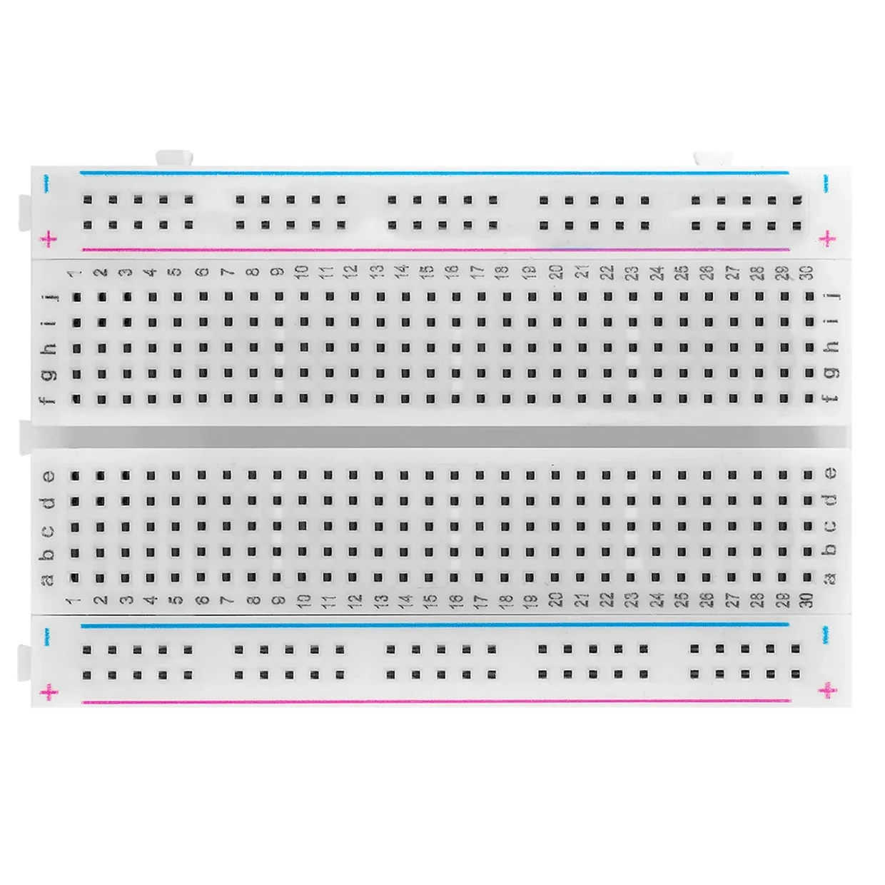
Large breadboard
A block of holes wired together underneath in a fixed pattern. Lay it down so the numbers run left to right: columns are numbered 1 to 63, rows are lettered a to j. Each column holds five joined holes above the channel and five below, and the four long rows along the top and bottom edges carry power the whole width of the board.
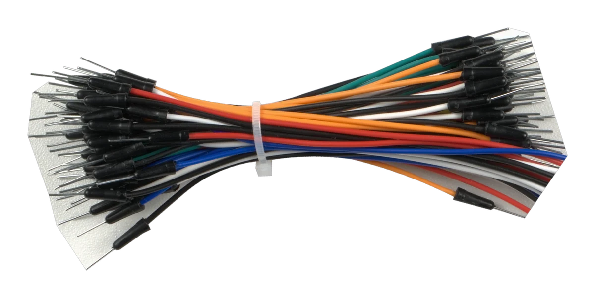
Jumper wire set
Short stiff wires for making connections. Colour means nothing to the circuit, but it means a lot to you. Use one colour per connection and a photograph of your board stays readable.
Passive parts
330 Ω resistor, 25 of them
Bands orange, orange, brown. Limits the current through an LED. One per LED, never shared.
An LED cannot limit its own current, so without a resistor the pin supplies as much as it can until the LED is damaged. Chapter 4 measures exactly what this resistor does, and tells you what your LED actually wants.

10 kΩ resistor, 15 of them
Bands brown, black, orange. Used as a pull-up for a button, as the fixed half of a divider with the photoresistor, as the charging resistor in the RC circuit, and as the base resistor for a transistor. Four different jobs in one value.

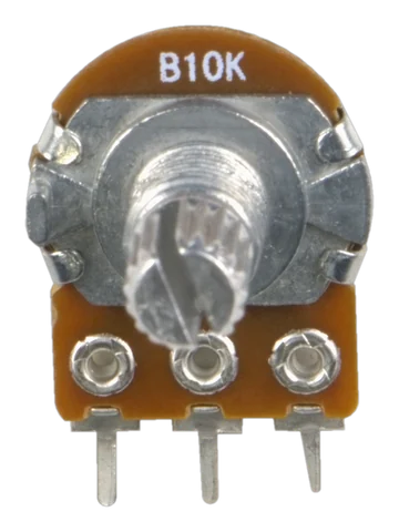
10 kΩ potentiometer, 3 of them
A resistor with a sliding contact. The two outer legs are the ends of a fixed track and the middle leg, the wiper, touches it somewhere between them. Wired across the supply it turns a knob into a voltage.
Legs are on a 5 mm pitch, so they land in alternate columns rather than adjacent ones.
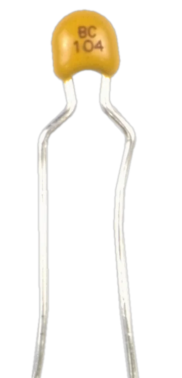
100 nF capacitor, 5 of them
Small yellow disc, no polarity, either way round. Two jobs in this kit: the fast half of the RC measurement, and decoupling, which means sitting right next to a chip's supply pins to absorb the current spike when its outputs all switch at once.
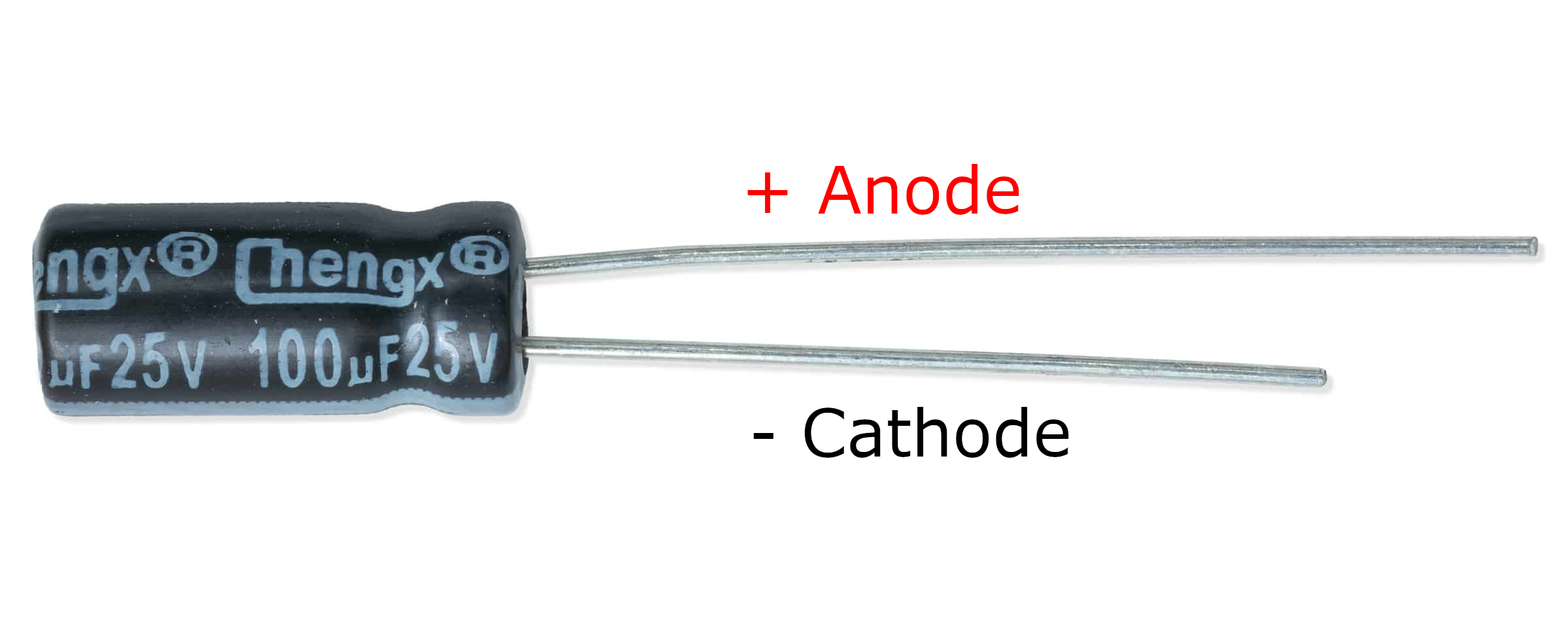
10 µF electrolytic capacitor, 5 of them
Small cylinder with a stripe down one side. Polarised: the leg next to the stripe is negative and goes to ground.
Things that light up and make noise
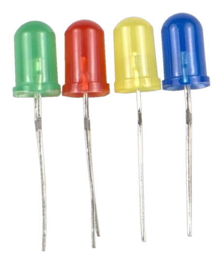
5 mm LED, 13 of them
Three each of red, yellow, green and blue, plus one RGB. Coloured domes with two legs. The long leg is the anode and goes towards the positive side; the short leg sits next to a flat spot on the rim. Lights in one direction only, and always through its own 330 Ω resistor.
Each colour needs a different voltage to light, so a blue LED looks dim in a circuit built around a red one. Chapter 4 measures yours.
The RGB one has four legs: one per colour, plus a common. It needs three resistors and three PWM pins. The manual drives the WS2812B already on the board instead, which needs one pin and no resistors, so this four-legged LED is spare and yours to experiment with.
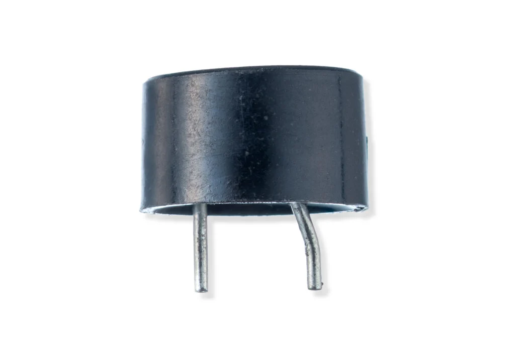
Buzzer QMB-09B-03
A passive buzzer: a coil inside pulls on a steel disc, and the disc springs back when the coil lets go. It makes no sound at all from a steady voltage, and the frequency of the signal you give it is the pitch.
Its legs are very short and one column apart, so plan where everything lands before pushing it in. It draws more than a pin should supply, so it is driven through a transistor.
Things that sense
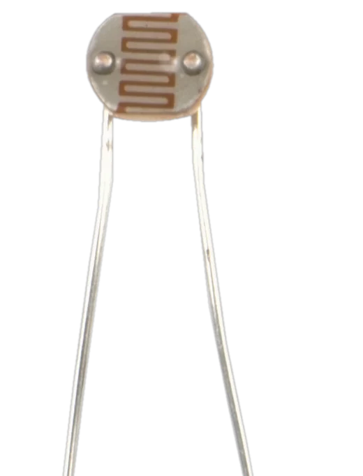
10 kΩ photoresistor, 5 of them
A resistor whose value falls as light hits it. Two legs, no polarity. In the dark it reaches hundreds of kilohms; under a bright light it drops to a few hundred ohms.
The board cannot measure resistance, only voltage, so it is always paired with a fixed resistor to make a divider.
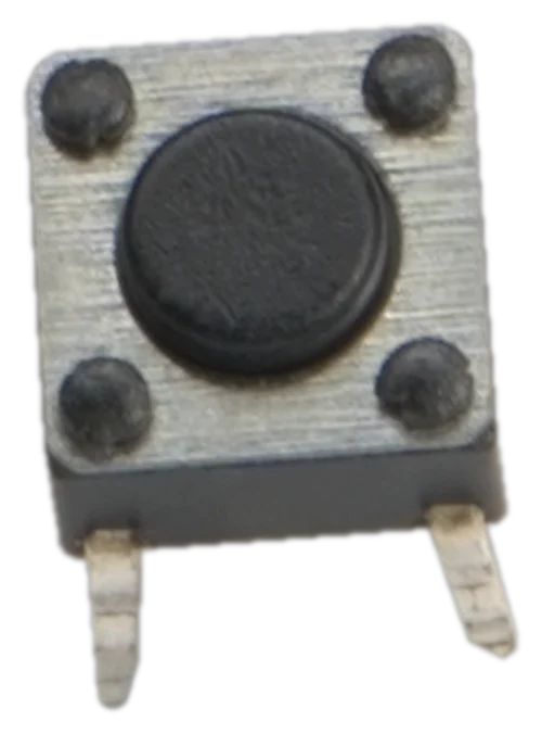
Small THT pushbutton, 5 of them
Four legs in two pairs. The two legs on the same side of the body are permanently joined to each other, and pressing joins one pair to the other.
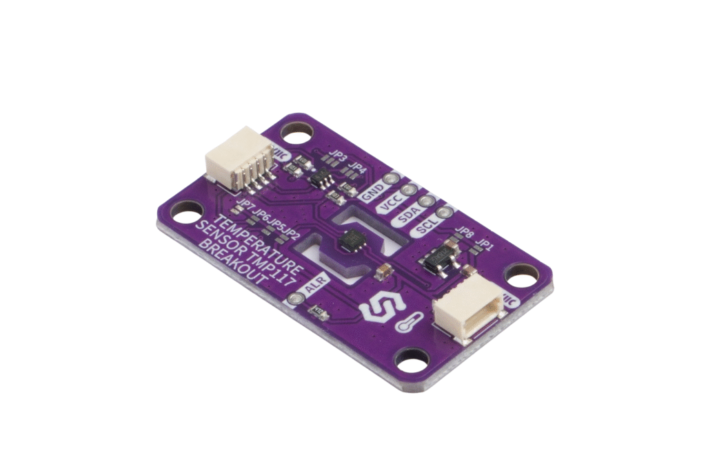
TMP117 temperature sensor
A precision temperature sensor on a Qwiic board. No wiring, one cable. It can also watch the temperature on its own and raise a flag when it leaves a band, which is what makes it useful to a board that spends its time asleep.
TMP117 temperature sensor
Accuracy, addresses, the alert output and the library.
Things that switch and move
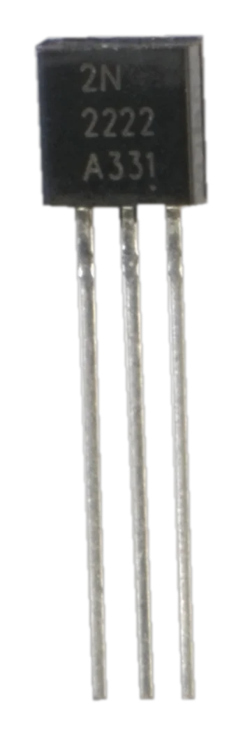
NPN transistor, TO-92, 5 of them
Lets a small current at the base control a much larger one from collector to emitter. Used as a switch for the buzzer and as the subject of its own chapter.
1N4148 diode, 5 of them
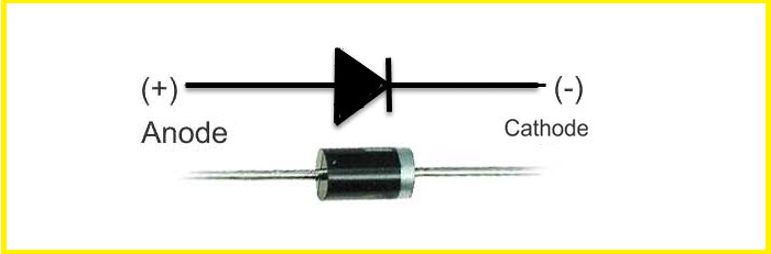
Conducts one way and blocks the other. The band marks the cathode, the end current flows out of. Used to measure what a diode actually does, and as flyback protection across the buzzer.
SN74HC595N shift register
A 16-pin chip that turns a sequence of bits into eight parallel outputs, so three pins drive eight LEDs. Orient it by the notch in the end of the package, not by any round dimple, which on this part is not at the pin 1 end.
It needs two things that give no obvious sign when they are missing: its master reset held high, and a 100 nF right at its supply pins.

SG90 servo
A motor, a gearbox, a position sensor and a controller in one box. You tell it where to be, not how fast to turn, using the width of a pulse repeated every 20 ms.
VCC, never from 3V3. 3V3 is a small regulator meant to run the chip, and starting a motor from it browns the board out.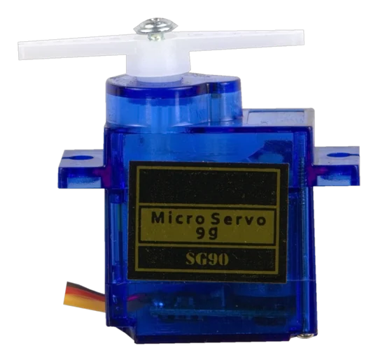
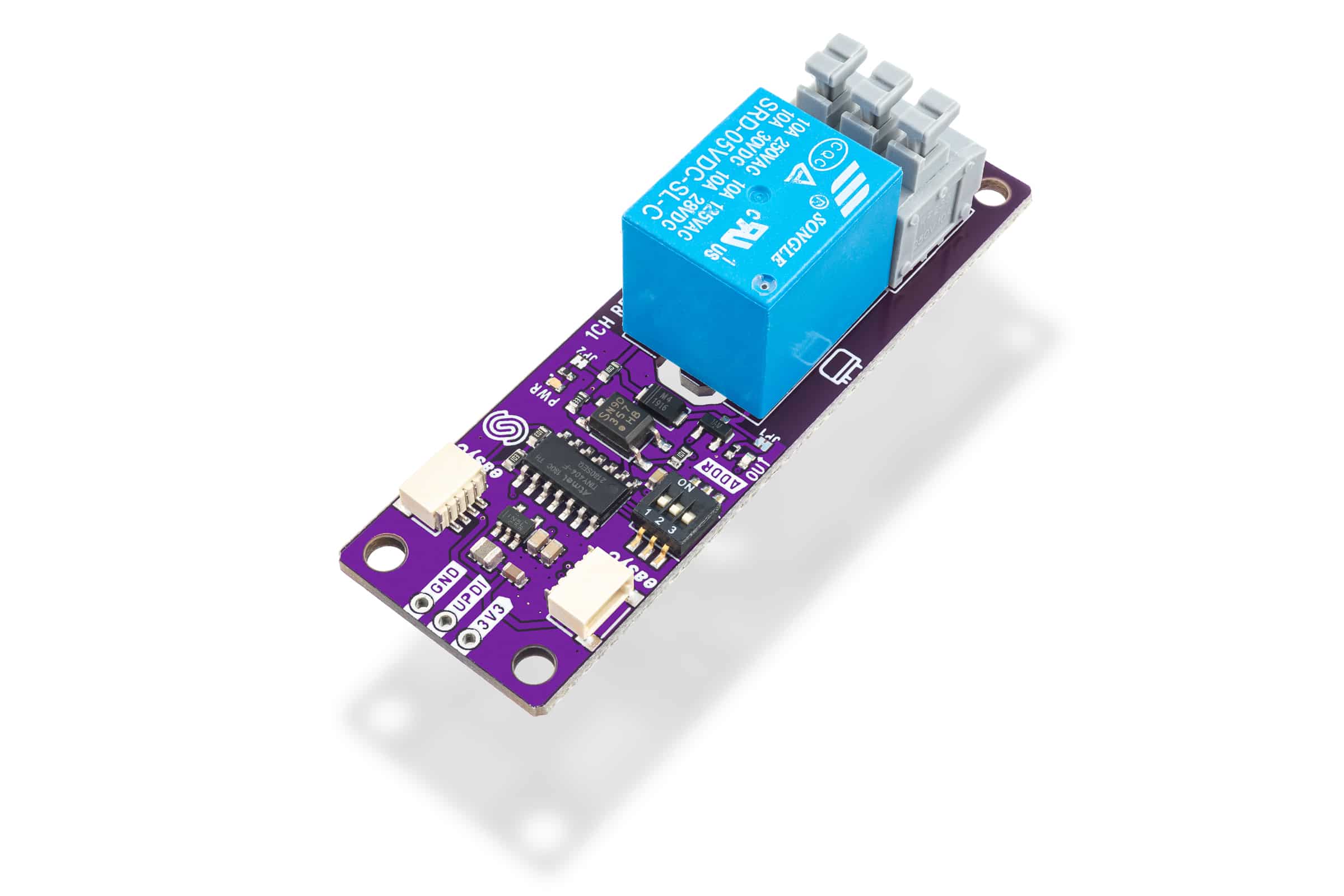
1-channel relay
A mechanical switch operated by an electromagnet, on a Qwiic board, with the coil driving and the isolation done for you. It is slow, it is audible, and it has a finite number of operations in it. That is why the examples work hard to switch it as rarely as possible.
1-channel relay
Contact ratings, the screw terminal and the library.
Connections
Qwiic cable, 10 cm, 5 of them
Four wires carrying power, ground and the two lines of an I2C bus. Every Qwiic module has two sockets, so modules chain, and the connector only fits one way.

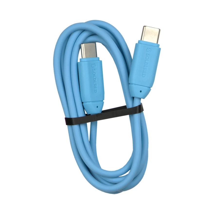
USB-C cable
Supplied with the kit. Programming and power over one lead. It is a data cable. A charge-only one gives you a board that never appears as a port, which is worth knowing if you ever reach for a different cable.
What is not in the box
No battery, and nothing here needs one. No meter either. The board measures its own circuits instead, and that is the idea the manual is built on.
Next
You have the parts. The manual takes you through them in order, one idea at a time, from a single blinking LED to four projects that use most of the box at once.