How it works
The Inputronic BRIDGE operates as a versatile USB-to-serial protocol translator powered by the ESP32-S3 microcontroller. When using our board, you are essentially communicating with the onboard ESP32-S3, which acts as a USB Host to read standard USB HID devices and output their data over I2C, UART, or SPI.
How the bridge works
The Inputronic BRIDGE simplifies the complex task of interfacing with USB devices. It operates by acting as a USB Host. When you plug in a compatible USB device (such as a keyboard, mouse, or MIDI controller) into the protected Female USB-A port:
- The onboard ESP32-S3 detects the device and enumerates it.
- It continuously receives raw USB HID reports and descriptors from the connected device.
- The custom firmware parses this complex USB data and translates it into a simplified, standardized data stream.
- The parsed data is then sent out to your main microcontroller via the selected communication protocol.
Key Features Explained
Multi-Protocol Output
The board is designed to adapt to your project's needs by supporting three different communication protocols. The active protocol is selected using the onboard hardware jumpers (JP3 & JP4):
- I2C (Default): Communicates over the standard
SDAandSCLpins. The default I2C slave address is0x50. This mode is perfect for chaining multiple devices and is readily accessible via the onboard Qwiic (formerly easyC) connectors. - UART: Transmits and receives data using standard serial communication via the
RXandTXpins. - SPI: Offers high-speed communication using the
MISO,MOSI,CLK, andCSpins.
Interrupt-Driven Data Reading
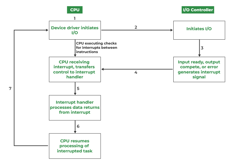
To optimize the performance of your main microcontroller, the Inputronic BRIDGE features an Interrupt (INT) output pin.
Instead of continuously polling the bus for new data (which wastes CPU cycles and bus bandwidth), your microcontroller can wait for the INT pin to trigger. The BRIDGE firmware automatically signals this pin whenever a new HID event (like a key press, mouse movement, or MIDI command) is parsed and ready to be read.
Advanced Data Modes & Event Parsing
The ESP32-S3 does the heavy lifting of parsing USB protocols. Using the dedicated open-source Arduino library, you can easily access:
- Parsed Events: Ready-to-use data structures like
KeyboardEvent,MouseEvent, andMIDIEvent. - Raw HID Data: For custom or non-standard USB devices, you can bypass the automatic parsing to request raw HID reports and raw USB descriptors, allowing you to manually process the data on your host microcontroller.