How it works
The Inputronic GRID is an interactive module featuring a 4x4 matrix of capacitive touch pads layered over 16 individually addressable RGB LEDs. It is designed to act as a complete human-machine interface, driven by its onboard ATtiny404 microcontroller.
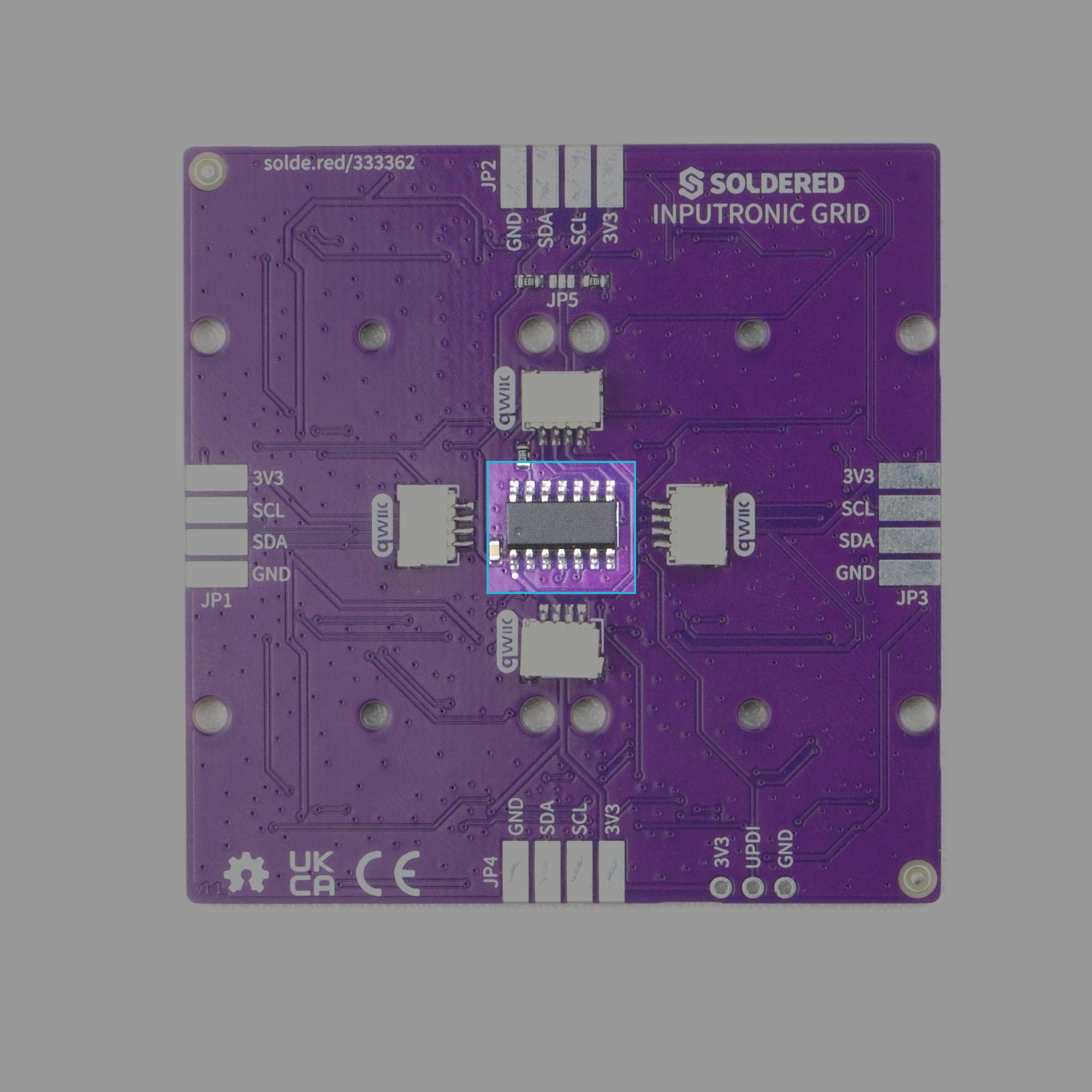
How the Inputronic GRID works
Rather than requiring your main microcontroller to constantly read 16 separate touch pins and precisely time the data signals for 16 WS2812B LEDs, the onboard ATtiny404 chip handles all the heavy lifting. It continuously scans the inputs and updates the outputs, acting as a bridge between the physical hardware and a simple I2C interface.
Capacitive Touch Scanning
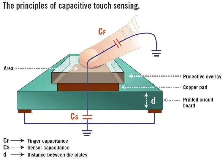
The board features 16 capacitive touch pads arranged in a 4x4 grid. The ATtiny404 continuously scans these pads using a column-scanning method to detect touches. It stores the current state of all 16 buttons (pressed or released) in its memory. When your main microcontroller requests the button states via I2C, the ATtiny instantly replies with the pre-read data.
Smart LED Control
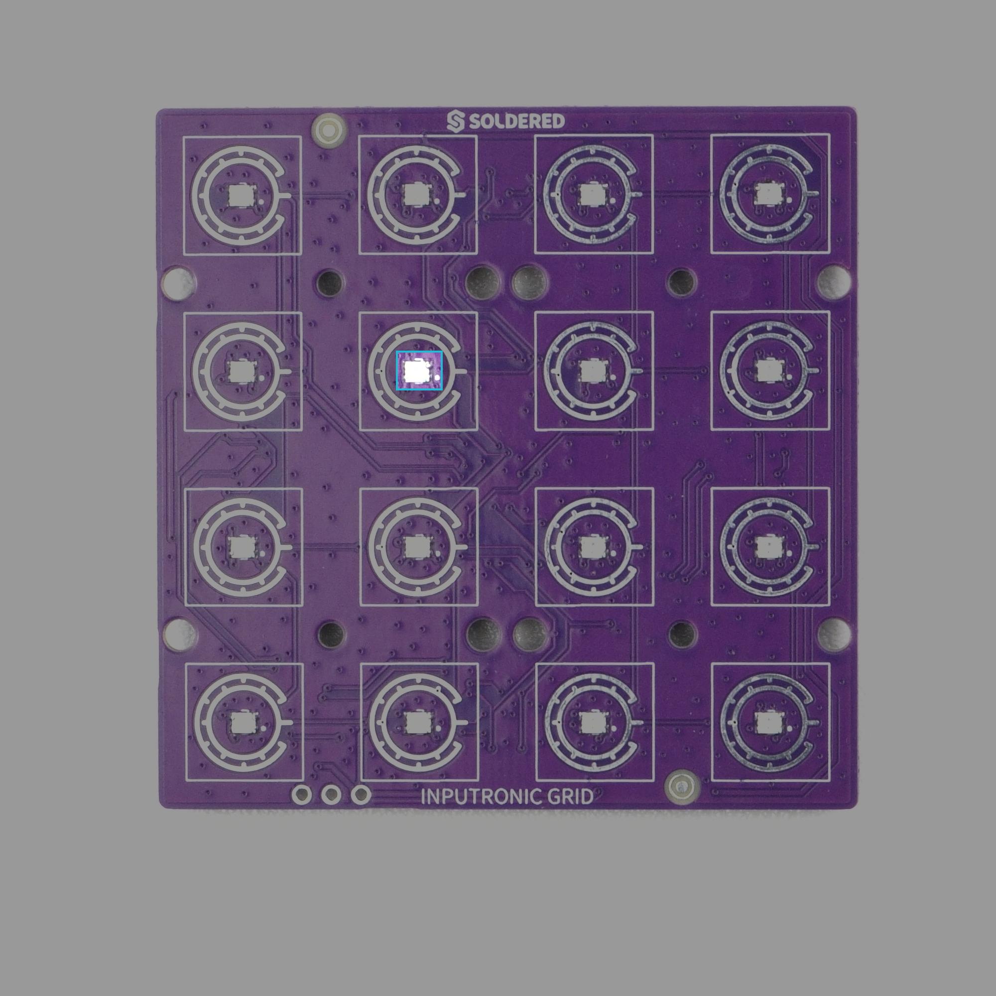
Underneath the touch matrix are 16 WS2812B-2020 RGB LEDs. These LEDs require strict timing to function, which can interrupt other processes on standard microcontrollers. The ATtiny404 manages this LED strip internally. You simply send an I2C command telling the ATtiny which LED to light up and in what color (using standard RGB values). The firmware automatically translates grid coordinates (row, column) into the correct physical LED index (which follows a serpentine layout on the board) and updates the colors seamlessly.
I2C Communication (Qwiic)
The board communicates entirely over I2C, making it fully compatible with the Qwiic (easyC) ecosystem, allowing seamless integration with microcontrollers without the need for complex wiring.
- Default I2C Address:
0x30 - Dynamic Addressing: Unlike traditional boards that use physical solder jumpers, the Inputronic GRID stores its I2C address in the ATtiny's internal EEPROM. You can send a software command to change this address on the fly, and the new address will persist across power cycles.
I2C Command Overview
The firmware uses a simple set of commands sent as the first byte of an I2C transaction to control the board:
| Command Byte | Function | Description |
|---|---|---|
| 0x01 | Set single LED | Sets the color (R, G, B) of a specific LED. |
| 0x02 | Set all LEDs | Sets all 16 LEDs to the same color. |
| 0x03 | Get single button | Queries the state of one specific button (returns 1 or 0). |
| 0x04 | Get all buttons | Retrieves a 16-bit mask representing the state of all buttons. |
| 0x05 | Set I2C Address | Writes a new I2C address to the EEPROM. |
| 0x06 | Set LED Mask | Lights up specific LEDs based on a 16-bit mask. |
grid.setLED(row, col, r, g, b) and grid.readPad(row, col).