Example usage with Arduino
This page provides examples of how to initialize and use the Inputronic GRID module with an Arduino.
Initialization
To use the Inputronic GRID, you need to include the library, create an instance of the InputronicGrid object, and initialize it within the setup() function. The begin() function establishes I2C communication, verifies that the module is connected, and should be checked before continuing with the rest of the sketch.
#include <InputronicGrid.h>

InputronicGrid grid;

void setup()
{
    Serial.begin(115200);
    while (!Serial)
        ;

    if (!grid.begin())
    {
        Serial.println("Inputronic GRID not found. Check wiring.");
        while (1)
            ;
    }

    Serial.println("Inputronic GRID ready.\n");
    grid.clearLEDs();
}
grid.begin()
Initializes the Inputronic GRID, starts I2C communication, and checks whether the module responds correctly on the bus.
Returns type: bool
Returns value: Returns true when the grid is detected and ready to use, or false when initialization fails.
Basic Readings
Here is a simple example that initializes the grid and continuously reads the state of all 16 buttons, printing the results to the Serial Monitor as a 4x4 matrix:
#include <InputronicGrid.h>

InputronicGrid grid;

void setup()
{
    Serial.begin(115200);
    while (!Serial)
        ;

    if (!grid.begin())
    {
        Serial.println("Inputronic GRID not found. Check wiring.");
        while (1)
            ;
    }

    Serial.println("Inputronic GRID ready.\n");
    grid.clearLEDs();
}

void loop()
{
    Serial.println("+---------+");
    for (uint8_t row = 0; row < 4; row++)
    {
        Serial.print("| ");
        for (uint8_t col = 0; col < 4; col++)
        {
            Serial.print(grid.readPad(row, col) ? 'X' : '.');
            Serial.print(' ');
        }
        Serial.println("|");
    }
    Serial.println("+---------+\n");

    delay(50);
}

grid.readPad(uint8_t row, uint8_t col)
Reads the current state of a specific capacitive touch pad based on its row and column coordinates.
Returns value: bool - Returns true if the pad is currently being pressed, false if it is released.
Function parameters:
| Type | Name | Description |
|---|---|---|
uint8_t | row | The row index of the pad (0 to 3). |
uint8_t | col | The column index of the pad (0 to 3). |
Advanced Example
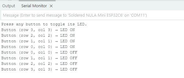
This example demonstrates a more interactive use case, where reading the buttons directly controls the corresponding LEDs. Each button toggles its specific LED on or off, with a unique color assigned to each row. This shows how to read individual pads by their row/col coordinate and react with per-LED color control.
void loop()
{
    for (uint8_t row = 0; row < 4; row++)
    {
        for (uint8_t col = 0; col < 4; col++)
        {
            bool pressed = grid.readPad(row, col);

            if (pressed && !prevState[row][col])
            {
                ledOn[row][col] = !ledOn[row][col];

                if (ledOn[row][col])
                    grid.setLED(row, col, rowColor[row][0], rowColor[row][1], rowColor[row][2], 255);
                else
                    grid.setLED(row, col, 0, 0, 0, 255);

                Serial.print("Button (row ");
                Serial.print(row);
                Serial.print(", col ");
                Serial.print(col);
                Serial.print(") → LED ");
                Serial.println(ledOn[row][col] ? "ON" : "OFF");
            }

            prevState[row][col] = pressed;
        }
    }

    delay(20);
}
grid.setLED(uint8_t row, uint8_t col, uint8_t r, uint8_t g, uint8_t b)
Sets the color of a specific individual LED on the grid using standard RGB values. The hardware handles mapping the matrix coordinates to the physical LED layout.
Returns value: void
Function parameters:
| Type | Name | Description |
|---|---|---|
uint8_t | row | The row index of the LED (0 to 3). |
uint8_t | col | The column index of the LED (0 to 3). |
uint8_t | r | Red brightness level (0 to 255). |
uint8_t | g | Green brightness level (0 to 255). |
uint8_t | b | Blue brightness level (0 to 255). |
Additional Functions
grid.setAddress(uint8_t newAddr)
Changes the I2C address of the device. The new address is validated, written to the onboard EEPROM, and immediately applied without requiring a physical reset. The new address persists across power cycles.
Returns value: void
Function parameters:
| Type | Name | Description |
|---|---|---|
uint8_t | newAddr | The new 7-bit I2C address to assign (must be within the valid range of 0x08 to 0x77). |