TXB0104 – How it works
The Logic Level Converter Board by Soldered enables safe voltage-level shifting between 3.3V and 5V logic systems, facilitating communication between devices with differing voltage requirements.
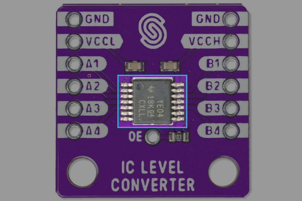
How it works
The TXB0104 is a bidirectional voltage-level translator that automatically adjusts the data direction without requiring a control signal. This makes it ideal for interfacing different logic levels in mixed-voltage systems.
Unlike traditional level shifters, the TXB0104 does not need a dedicated direction-control signal. Instead, it dynamically detects the direction of data flow:
- When data transitions from A to B or B to A, the device automatically adapts.
- The output drivers are weakly driven in a DC state, allowing an external driver to override them when the data flow reverses.
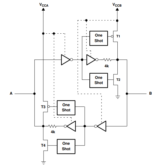
The TXB0104 includes one-shot edge accelerators to enhance signal transitions:
- Rising Edge: The one-shot circuit activates PMOS transistors (T1, T3) briefly, speeding up the transition from low to high.
- Falling Edge: The one-shot circuit activates NMOS transistors (T2, T4) briefly, ensuring a faster high-to-low transition.
Enable and Disable
The TXB0104 has an OE input that is used to disable the device by setting OE = low, which places all I/Os in the high-impedance (Hi-Z) state. The disable time (tdis) indicates the delay between when OE goes low and when the outputs are actually disabled (Hi-Z). The enable time (ten) indicates the amount of time the user must allow for the one-shot circuitry to become operational after OE is taken high.
How to connect it?
- Connect Power:
- Connect HVCC to the high-voltage power source (e.g., 5V) and LVCC to the low-voltage source (e.g., 3.3V).
- Connect GND to the ground of both the high and low-voltage systems.
- Wiring the Signals:
- Connect the B1-B4 pins to the high-voltage signal lines from your device (e.g., a 5V microcontroller).
- Connect the A1-A4 pins to the low-voltage signal lines (e.g., a 3.3V sensor).
- Verify Connections:
- Ensure the correct orientation and check that each signal is connected to the proper high- or low-voltage side.