How it works
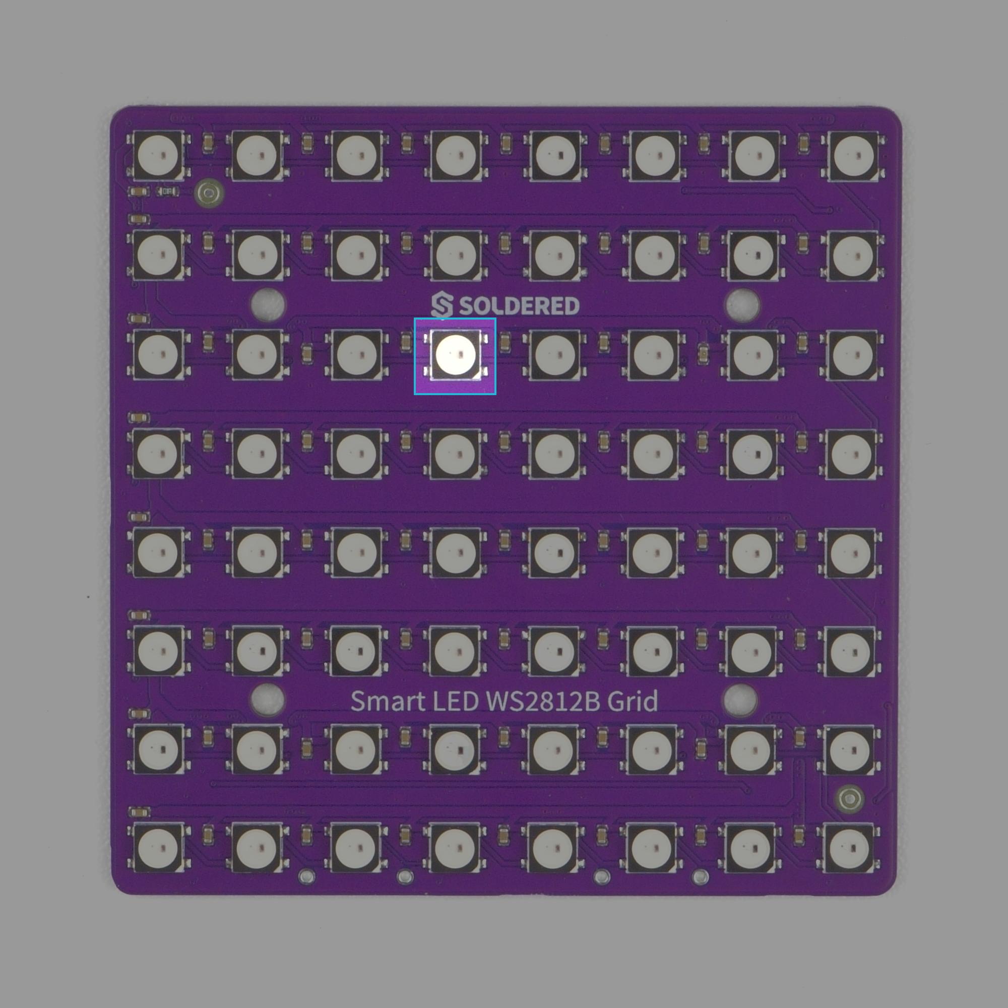
The Smart LED WS2812B Grid 8x8 is a circuit board that contains a system of 64 daisy-chained WS2812B RGB LEDs arranged in a 8x8 grid layout. Each LED contains an integrated driver IC, allowing every pixel to be individually addressable and controlled through a single data line.
Datasheet
For an in-depth look at technical specifications, refer to the official WS2812B Datasheet:
WS2812B Datasheet
Detailed technical documentation for WS2812B LED
How the LEDs work
Each WS2812B LED combines three LEDs (red, green, and blue) and a built-in control IC inside a single package. The control IC receives digital data from the microcontroller and determines the brightness of each color channel using PWM (Pulde Width Modulation).
The LEDs are connected in a serial daisy-chain configuration, there the output (DOUT) of one LED is connected to the data input (DIN) of the next LED.
The microcontroller sends a stream od 24-bit color data for each LED:
- 8 bits for green
- 8 bits for red
- 8 bits for blue
The first LED reads the first 24 bits meant for it, stores that data internally, and forwards the remaining data to the next LED in the chain.
Communication Protocol
The Ws2812B uses a single-wire serial communication protocol with strict timing requirements.
Unilke SPI or I2C, communication is based on Pulse Width Timing, where a logic 1 is represented by a longer HIGH pulse and logic 0 is represented by a shorter HIGH pulse. Each bit is transmitter in approximately 1.25 us.