BHI385 Smart IMU - How it works
The BHI385 is a Smart IMU from Bosch Sensortec. Unlike a typical accelerometer or gyroscope where you read a pair of registers, using the BHI385 involves uploading a firmware binary into the chip's program RAM, enabling virtual sensors by name, and reading processed motion data from a pair of hardware FIFOs. Every output (rotation quaternion, step count, tap event, wrist gesture) comes from algorithms running on the chip's internal Fuser2 processor, not your microcontroller.
Datasheet
For full electrical specifications, register maps, and firmware protocol details, refer to the official BHI385 datasheet:
BHI385 Datasheet
Complete technical reference for the Bosch BHI385 Smart IMU, including register maps, electrical characteristics, and firmware protocol.
How the Smart IMU works
While traditional IMUs rely entirely on a host processor to crunch sensor data, the BHI385 handles everything locally on the chip itself hence Smart in the name. It has accelerometer that converts physical acceleration into a differential capacitance signal: a proof mass suspended by spring structures shifts position when the chip accelerates, and the capacitance between that mass and fixed electrodes changes in proportion. The gyroscope uses the Coriolis effect: a vibrating structure deflects perpendicular to its oscillation axis when the chip rotates, and that deflection is sensed capacitively. Both signals are digitised by internal ADCs and passed to the Fuser2 core for processing.

The firmware running on the Fuser2 core processes those raw ADC values through several virtual sensor algorithms. The corrected accelerometer and gyroscope virtual sensors apply calibration coefficients and bias removal. The Game Rotation Vector fuses accelerometer and gyroscope data to produce a normalized quaternion (x, y, z, w) representing the device's 3D orientation. Pitch and roll are gravity-referenced; yaw is relative to power-on orientation since there is no magnetometer. The step counter uses an adaptive pedometer algorithm to increment a cumulative count as the sensor detects the characteristic acceleration signature of a footstep. The multi-tap and wrist gesture detectors classify short impulse patterns or continuous motion trajectories into named events (single tap, double tap, wrist shake, arm flick).
The BHI385 has no on-chip flash, so none of the firmware persists through a power cycle. On every power-on, the host must upload the firmware binary into the chip's program RAM before any virtual sensors will produce data. The library's loadFirmware() function handles this automatically; the chip's ROM bootloader verifies the upload via CRC and then boots the internal processor.
I2C communication and FIFO architecture
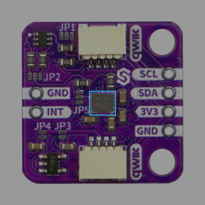
The BHI385 uses I2C at a default address of 0x29 (HSDO tied high) or 0x28 (HSDO tied low). The board's NMOS-dual level-shifter bridges the chip's 1.8V I2C bus to the 3.3V host interface, so you connect normally to the Qwiic (formerly easyC) connector or pin header without any additional circuitry.
Unlike most I2C sensors, the BHI385 does not use a register map for sensor data. All readings and events are delivered through an internal FIFO system. The library's update() call drains the FIFOs and dispatches each event to the appropriate data field, so you never need to manage the underlying communication yourself.