Multiple grids
Two or more grids can be wired into a single chain and driven from one microcontroller pin. The library treats the whole chain as one large coordinate space, so a pair of 8x8 boards side by side becomes a 16x8 grid with x running from 0 to 15.
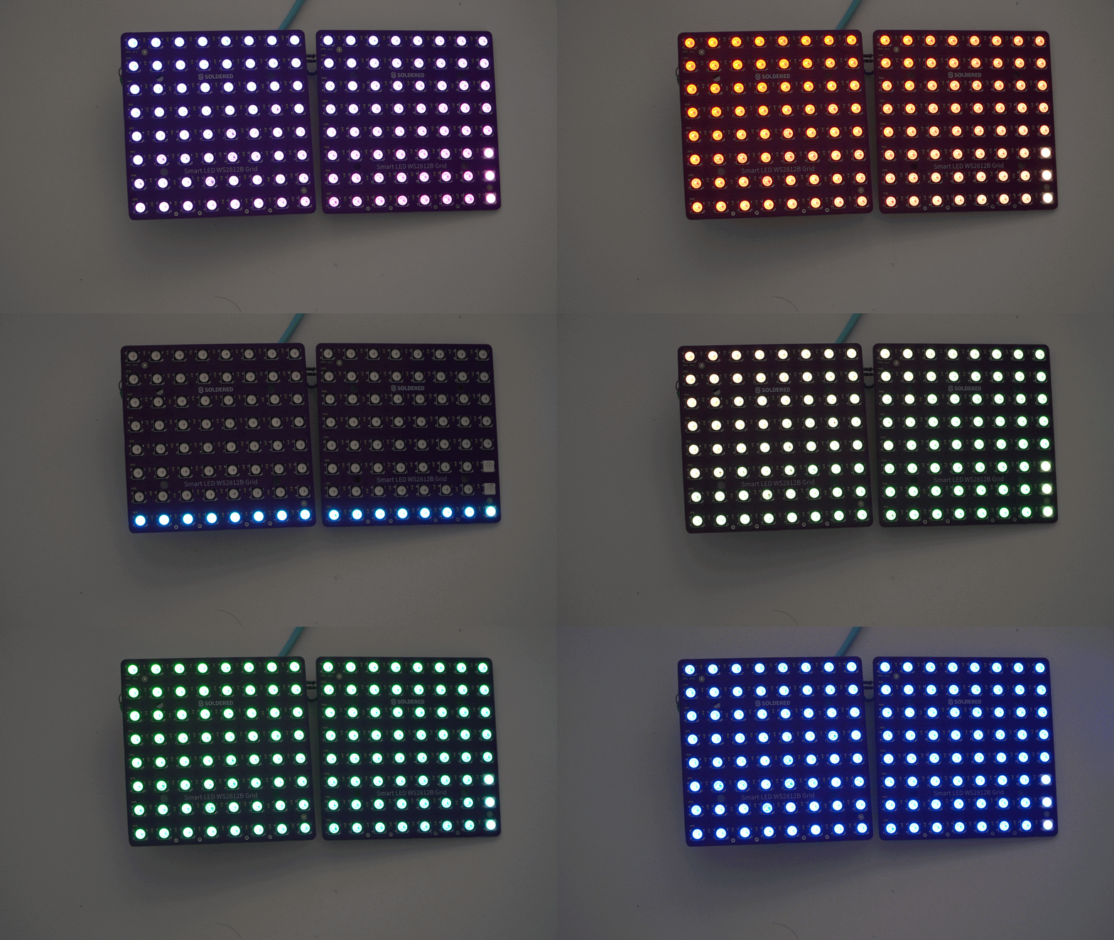
Wiring the chain
Each board has a DIN pad and a DOUT pad. Data enters a board at DIN, passes through all 64 LEDs, and leaves at DOUT. Connecting DOUT of one board to DIN of the next extends the daisy chain across boards exactly the way it runs inside a single board.
| NULA Mini | First grid | Second grid |
|---|---|---|
| IO4 | DIN | |
| GND | GND | GND |
| 5V supply | VCC | VCC |
| DOUT | DIN |
Telling the library the chain size
The WS2812Grid constructor takes the total width and height of the assembled surface. For two boards placed side by side that is 16 columns by 8 rows.
#include "WS2812Grid-SOLDERED.h"

#define PIN         4
#define GRID_WIDTH  16
#define GRID_HEIGHT 8

WS2812Grid grid(PIN, GRID_WIDTH, GRID_HEIGHT);

void setup()
{
    grid.begin();
    grid.setBrightness(40); // 0 to 255, keep it low on a multi-grid chain
}
grid.setBrightness()
Scales the output of every LED in the chain. This is the main current limiter on a multi-grid setup: brightness scales the PWM duty of all channels, so halving it roughly halves the supply current.
Returns value: None
Function parameters:
| Type | Name | Description |
|---|---|---|
uint8_t | brightness | Maximum brightness, 0 to 255. A value of 0 blanks the display. |
Which board is first in the chain
The order in which you wire the boards decides which physical panel owns which coordinates. The library numbers panels column first: every panel in the leftmost panel column, top to bottom, comes first in the data chain, then the next panel column, and so on.
For a 16x8 surface built from two boards there is only one panel row, so the order is simply left then right:
| Chain position | Panel | Covers |
|---|---|---|
| 1 (DIN from microcontroller) | Left | x = 0 to 7 |
| 2 | Right | x = 8 to 15 |
For an 8x16 surface built by stacking two boards vertically, the order is top then bottom:
| Chain position | Panel | Covers |
|---|---|---|
| 1 (DIN from microcontroller) | Top | y = 0 to 7 |
| 2 | Bottom | y = 8 to 15 |
For a 16x16 surface built from four boards, the chain walks down the left column of panels first, then down the right column:
| Chain position | Panel |
|---|---|
| 1 (DIN from microcontroller) | Top left |
| 2 | Bottom left |
| 3 | Top right |
| 4 | Bottom right |
xyToIndex() performs this mapping and is public, so you can inspect it or use the raw linear index directly:
void setup()
{
    Serial.begin(115200);
    grid.begin();

    // First LED of the second board in a 16x8 chain
    Serial.println(grid.xyToIndex(8, 0)); // prints 64

    // Out of range returns 0xFFFF
    Serial.println(grid.xyToIndex(20, 0), HEX); // prints FFFF
}
grid.xyToIndex()
Converts a coordinate on the assembled surface to the linear LED index within the chain. Panels are 8 by 8 and numbered column first, and within each panel the wiring is serpentine, so even local rows run left to right and odd local rows run right to left. Returns 0xFFFF when the coordinate falls outside the declared width or height.
Returns value: uint16_t LED index from 0 to width times height minus one, or 0xFFFF if the coordinate is out of range.
Function parameters:
| Type | Name | Description |
|---|---|---|
uint8_t | x | Column index across the whole surface, 0 = leftmost column of the first panel column. |
uint8_t | y | Row index across the whole surface, 0 = top row. |
Both width and height must be multiples of 8, because xyToIndex() derives the panel count from them. Declaring a 12x8 grid, for example, produces coordinates that do not correspond to any physical LED.
Drawing across the whole surface
Nothing about setPixel(), fill(), clear(), and show() changes on a chained setup. Address any pixel by its coordinate on the assembled surface and the library routes it to the right board.
void loop()
{
    grid.clear();

    // Left board
    grid.setPixel(0, 0, 255, 0, 0);

    // Right board, addressed in the same coordinate space
    grid.setPixel(15, 7, WS2812Grid::Color(0, 0, 255));

    // A line straight across the seam between the two boards
    for (uint8_t x = 0; x < GRID_WIDTH; x++)
        grid.setPixel(x, 3, 0, 180, 60);

    grid.show();
    delay(1000);
}
grid.show()
Clocks the buffered pixel data out of the data pin to the whole chain in one transfer. Every board updates from a single call, so there is no need to refresh them individually.
Returns value: None
Full example: animations across a 16x8 chain
This is the Animations example from the library scaled to two chained boards. Only the three defines at the top differ from the single board version: the loops read their bounds from GRID_WIDTH and GRID_HEIGHT, so the row sweep now runs 16 LEDs wide and the rainbow spreads its hue offset over the full surface.
#include "WS2812Grid-SOLDERED.h"

#define PIN 4
#define GRID_WIDTH 16
#define GRID_HEIGHT 8

WS2812Grid grid(PIN, GRID_WIDTH, GRID_HEIGHT);

static uint32_t colorWheel(uint8_t pos)
{
    pos = 255 - pos;
    if (pos < 85)
        return WS2812Grid::Color(255 - pos * 3, 0, pos * 3);
    if (pos < 170)
    {
        pos -= 85;
        return WS2812Grid::Color(0, pos * 3, 255 - pos * 3);
    }
    pos -= 170;
    return WS2812Grid::Color(pos * 3, 255 - pos * 3, 0);
}

void rowSweep()
{
    for (uint8_t y = 0; y < GRID_HEIGHT; y++)
    {
        grid.clear();
        for (uint8_t x = 0; x < GRID_WIDTH; x++)
        {
            grid.setPixel(x, y, 0, 180, 255);
        }
        grid.show();
        delay(80);
    }
}

void rainbowGrid(uint8_t cycles)
{
    for (uint8_t c = 0; c < cycles; c++)
    {
        for (uint16_t hue = 0; hue < 256; hue++)
        {
            for (uint8_t y = 0; y < GRID_HEIGHT; y++)
            {
                for (uint8_t x = 0; x < GRID_WIDTH; x++)
                {
                    uint8_t offset = (x + y * 2) & 0xFF;
                    grid.setPixel(x, y, colorWheel((hue + offset) & 0xFF));
                }
            }
            grid.show();
            delay(10);
        }
    }
}

void setup()
{
    grid.begin();
    grid.setBrightness(40);
}

void loop()
{
    rowSweep();
    delay(200);
    rainbowGrid(2);
    delay(200);
}
To stack the same two boards vertically instead, swap the defines to GRID_WIDTH 8 and GRID_HEIGHT 16 and rewire so the top board receives DIN from the microcontroller. The animation code needs no other change.