Inkplate 13SPECTRA – Free GPIO pins
Inkplate 13SPECTRA's onboard ESP32-S3-WROOM-2 has some pins reserved for internal use (for example, the connection to the e-paper display) and cannot be used for end-user applications. This page contains a list of the available GPIO pins that can be used for external applications.
If you don't need pin details and are just interested in the pins, here are the Inkplate 13SPECTRA pins that are not connected to any onboard component: IO17, GPIO Expander: P0-0 to P0-7, P1-0, P1-3 to P1-7
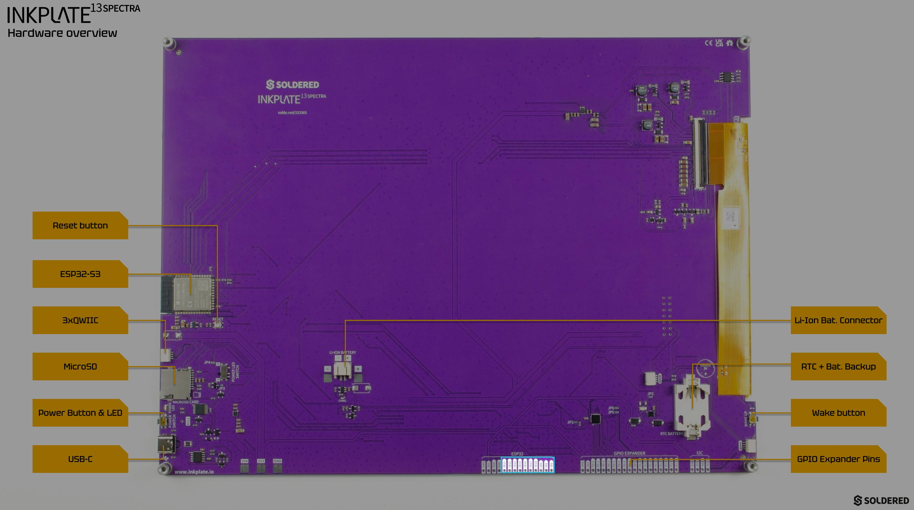
Inkplate 13SPECTRA ESP32 header
See the table below for pin functions and what each pin is connected to:
Free pin table
| PIN | CONNECTED TO | FUNCTION |
|---|---|---|
| TXD | CH340 | UART transmit pin, used to upload code and for Serial communication over USB |
| RXD | CH340 | UART receive pin, used to upload code and for Serial communication over USB |
| IO11 | SDCARD | SPI MOSI line for the onboard microSD card slot |
| IO12 | SDCARD | SPI SCK (clock) line for the onboard microSD card slot |
| IO13 | SDCARD | SPI MISO line for the onboard microSD card slot |
| IO15 | JP4 Check jumper details | Open (not connected) by default. When JP4 is shorted, this pin becomes the microSD card's SPI chip select line |
| IO16 | JP1 Check jumper details | Connected by default (JP1 is normally closed) to the onboard IO expander's interrupt pin |
| IO17 | FREE | No onboard connection |
| IO18 | WAKE button | Pulled high through a resistor and pulled low when the onboard wake button is pressed |
| IO0 | Auto-reset circuit | Driven low through the auto-reset circuit (alongside DTR/RTS) to enter the bootloader during upload; also an ESP32-S3 strapping pin, so avoid holding it low at boot for other purposes |
| IO2 | JP2 Check jumper details | Open (not connected) by default. When JP2 is shorted, this pin is connected to the onboard RTC's clock output |
| P0-0 to P0-7 | FREE | General-purpose IO expander pins, controlled over I2C |
| P1-0 | FREE | General-purpose IO expander pin, controlled over I2C |
| P1-1 | JP5 Check jumper details | Open (not connected) by default. When JP5 is shorted, this pin connects to the battery voltage measurement circuit |
| P1-2 | JP6 Check jumper details | Connected by default (JP6 is normally closed) to the MOSFET that powers the onboard microSD card |
| P1-3 to P1-7 | FREE | General-purpose IO expander pins, controlled over I2C |
| INT | IO16 Check jumper details | IO expander interrupt output, pulled up onboard; connected to ESP32 IO16 when JP1 is shorted |