2.1 Button Counter
So far the board has only been talking. In this example it starts listening: you will read a push button with the Soldered NULA MINI board and count how many times it has been pressed, printing the running total to the console.
In this documentation you will learn:
- How to wire a button with no extra components, using the resistor built into the chip
- How to configure a pin as an input with
Pin.INandPin.PULL_UP - How to read that pin with
value() - Why a pressed button reads 0 rather than 1
Hardware required:
- 1x Soldered NULA MINI board
- 1x Breadboard
- 1x Push button
- 2x Jumper wires
- 1x USB-C cable
Putting the components together
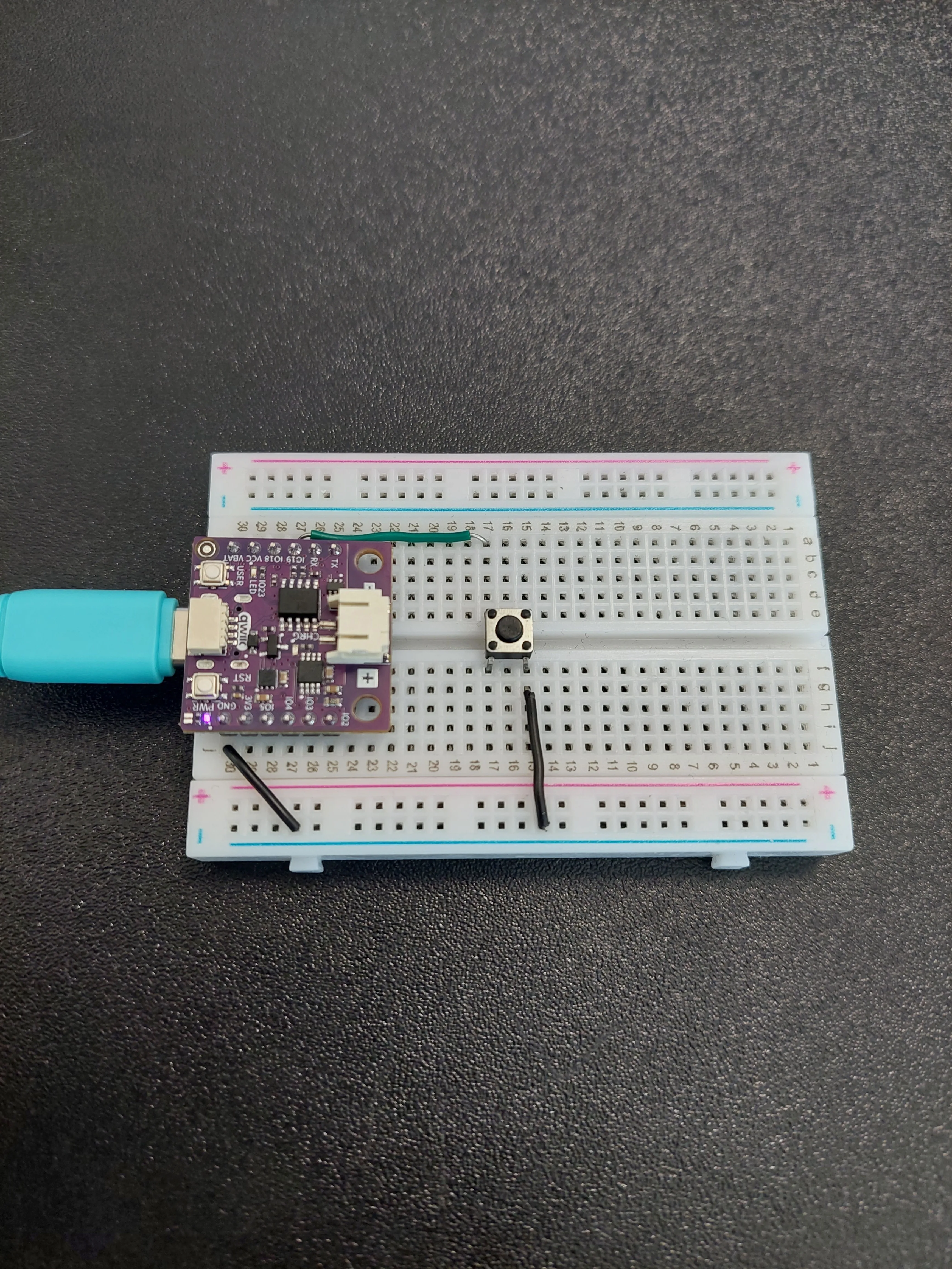
Follow the five steps below. Each photo is taken from the same position, so you can compare it with the previous one and see exactly what changed.
1. Insert the NULA MINI board on the breadboard
Push the board into one end of the breadboard so that its two rows of pins sit on either side of the centre channel, with the chip facing down. Press it in evenly until all the pins are seated.
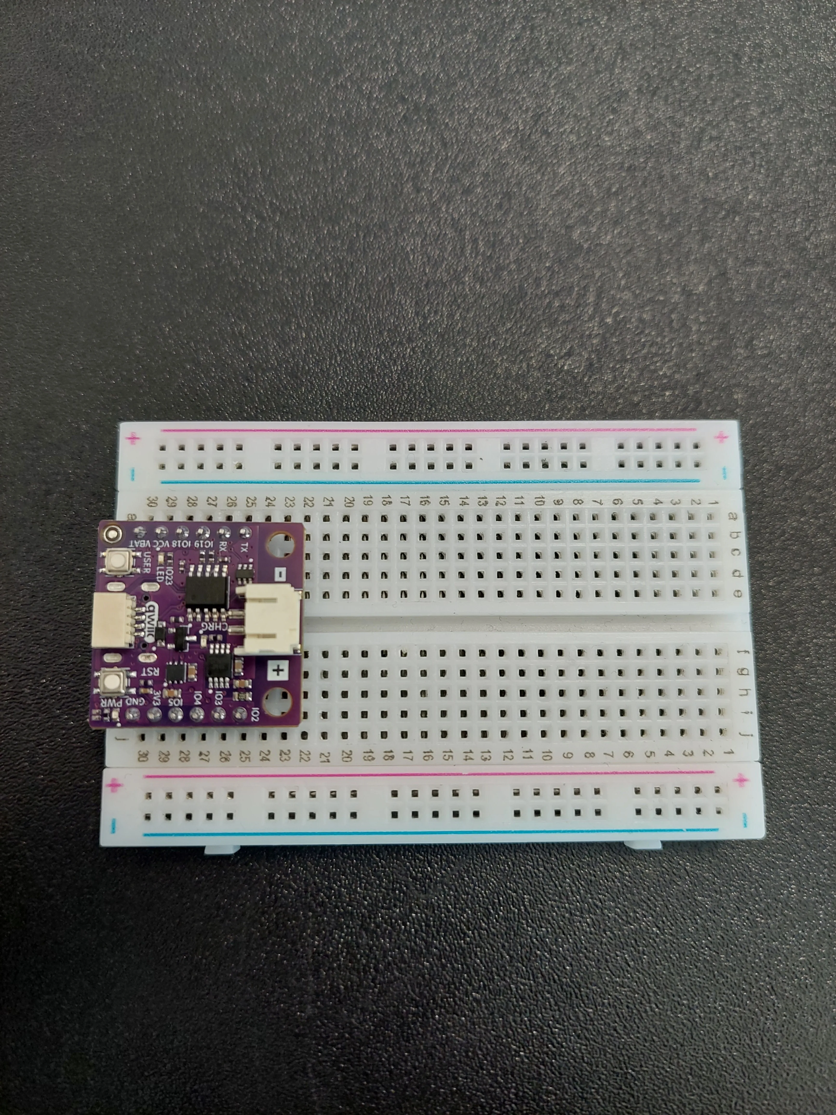
Take a moment to find the two pins this example uses. The pin names are printed along both edges of the board, and each pin sits in its own numbered row. In the photo above the board occupies rows 25 to 30, which puts IO19 in row 27 and GND in row 30.
2. Place the push button
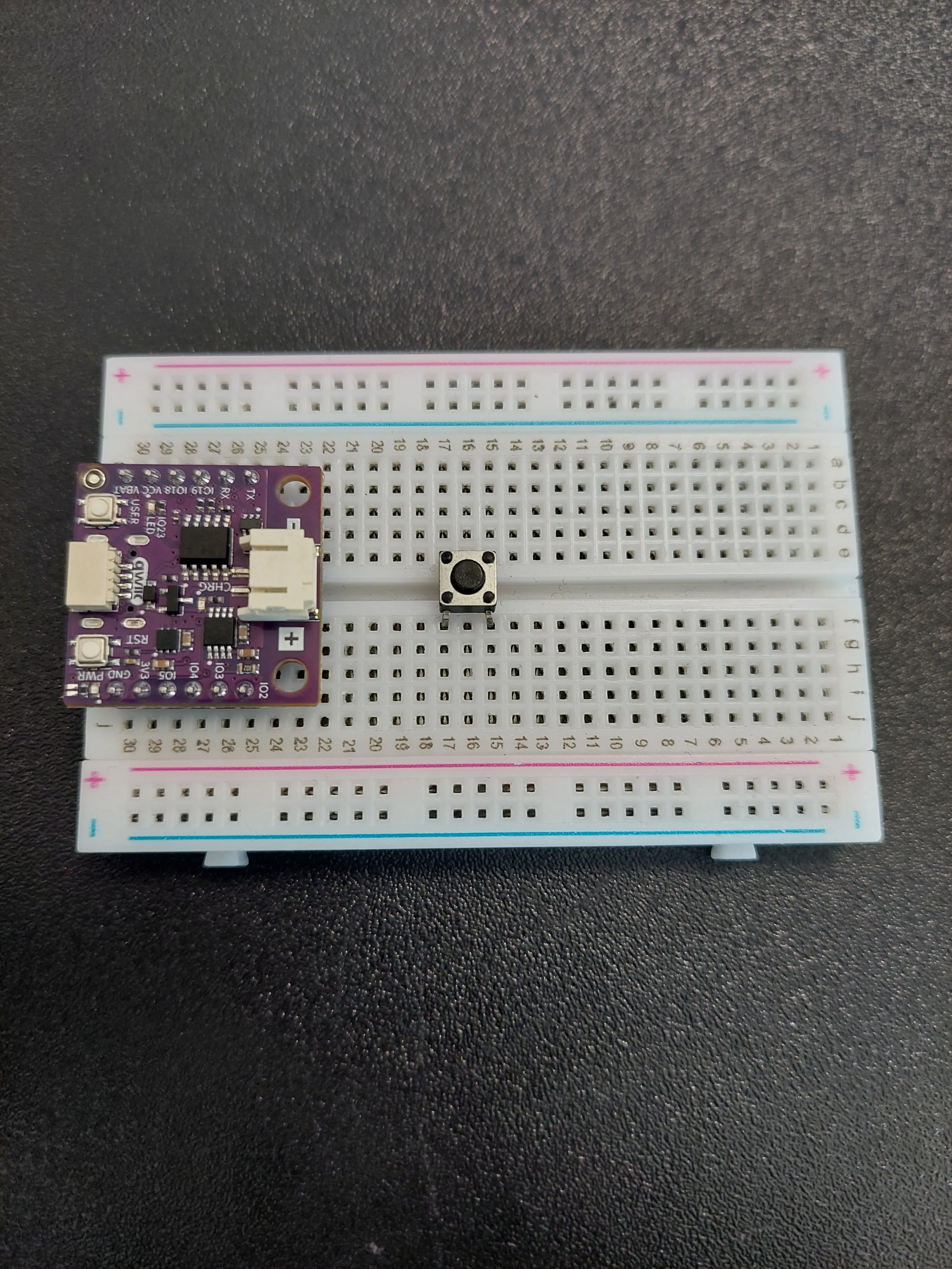
Push the button into the middle of the breadboard so that it straddles the centre channel, a few rows clear of the board. In the photo its legs are in rows 15 and 17.
3. Connect GND to the button
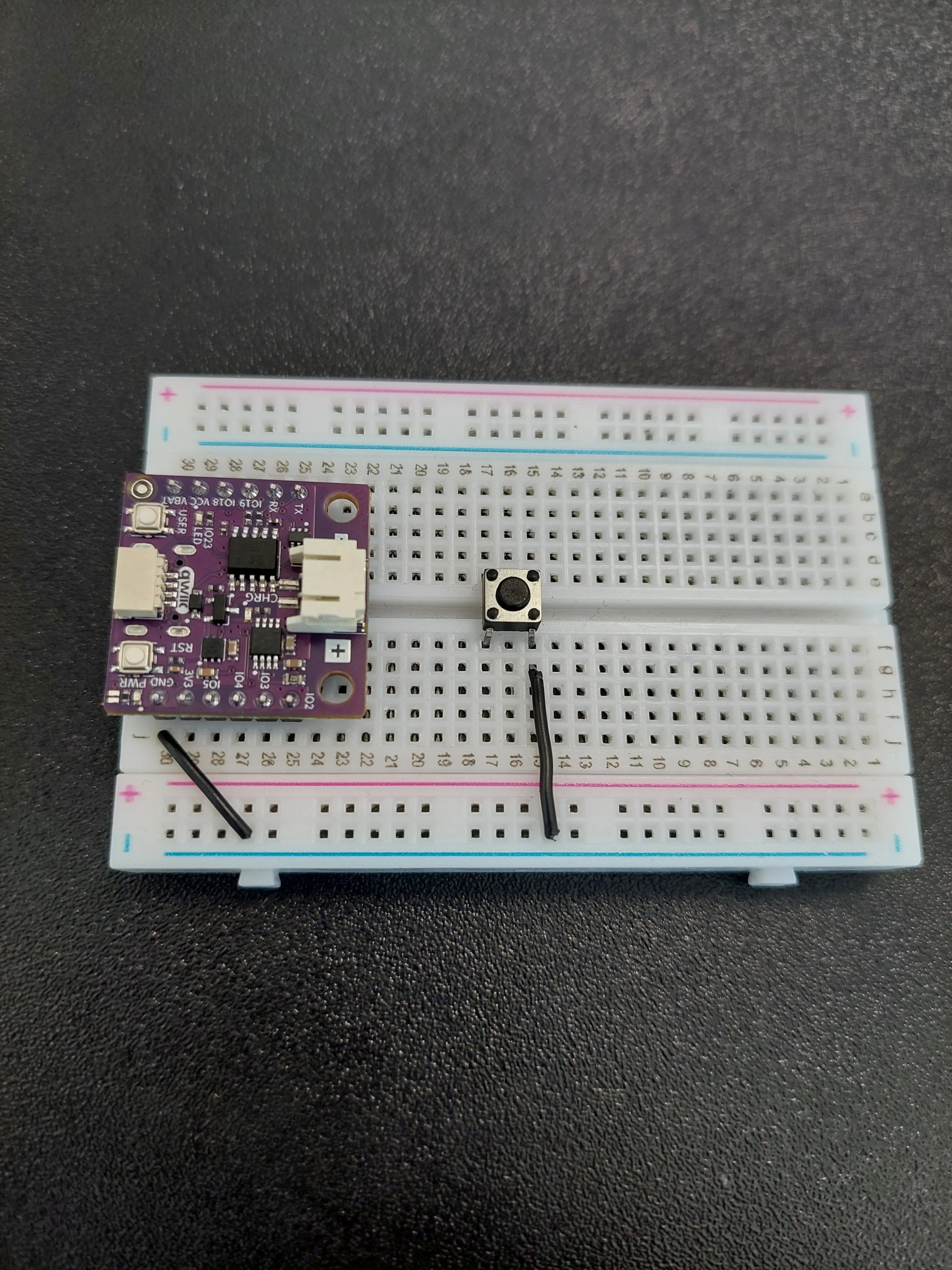
Ground goes across in two hops, using the blue − rail along the edge of the breadboard as a shared ground line.
- First jumper: from the row holding GND (row 30 in the photo) out to the blue − rail.
- Second jumper: from that same blue − rail back to row 15, on the f–j side of the button.
4. Connect IO19 to the button
Now the signal wire. Run a single jumper from the row holding IO19 (row 27 in the photo) to row 17, on the a–e side of the button.
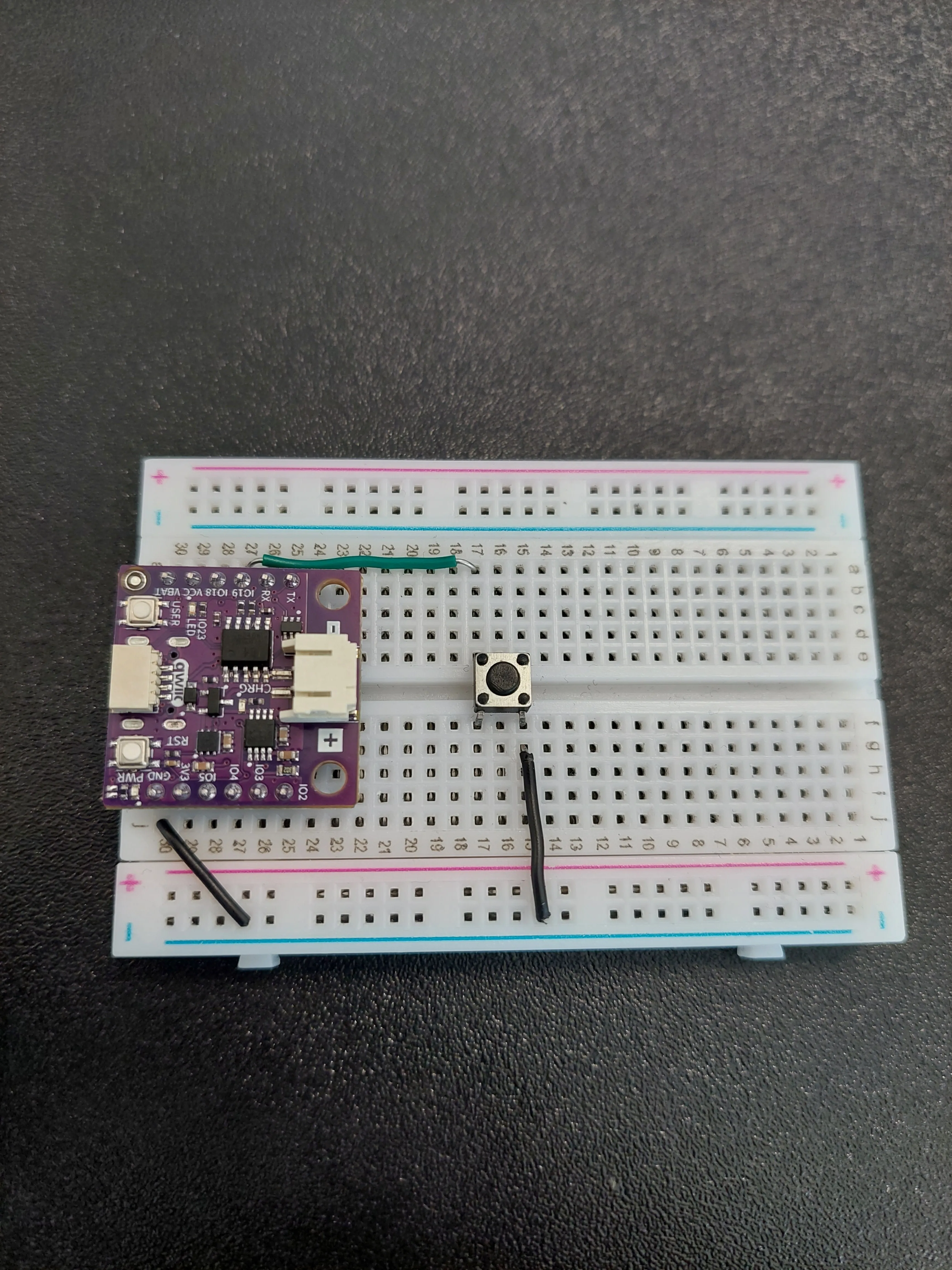
Notice that the two wires reach the button from opposite sides: row 15 on the f–j side, row 17 on the a–e side. That is the diagonal pair described above, and it is what makes the button actually switch something.
5. Connect the board to your computer
Plug the USB-C cable into the board. The power LED lights up as soon as it has power.
Reading an input
An output pin is one the board drives; an input pin is one it measures. In 1.2 LED Blinking the pin was created with Pin.OUT because we wrote to it. Here we want the opposite, so the pin is created with Pin.IN, and value() reports what it finds as either 1 (high) or 0 (low).
A pin that is connected to nothing at all is a problem: it is said to be floating, and it picks up enough electrical noise from its surroundings to flip between high and low on its own. The board would count presses that never happened. The pin needs something holding it at a known value whenever the button is not doing anything.
That is what Pin.PULL_UP is for. It switches on a resistor inside the chip that gently ties the pin to 3.3 V, so the pin reads 1 while nothing else is going on. The job of the button is only to connect that pin to GND, which overrules the weak internal resistor and drags the pin down to 0 V.
btn = Pin(BUTTON_PIN, Pin.IN, Pin.PULL_UP)
pinMode(BUTTON_PIN, INPUT_PULLUP) inside setup(). MicroPython folds both into the one line above: the third argument to Pin() is what switches the pull-up on.Counting the presses
Because there is no loop() in MicroPython, we write our own endless loop and read the button inside it. When the reading is 0 the button is down, so we add one to the counter and print the new total.
The += operator is shorthand for "add to what is already there", so counter += 1 means the same as counter = counter + 1.
if reading == 0:
    counter += 1
    print("Counter:", counter)
print() separated by commas prints them on one line with a space in between, so print("Counter:", counter) produces Counter: 4. That saves you from having to join the text and the number together yourself.Left like that, holding the button down would send the counter racing upward, because the loop would find the button still pressed on every pass. So after counting a press we wait for the button to come back up before carrying on:
while btn.value() == 0:
    # Wait until the button is released
    time.sleep_ms(10)
reading == 0 alone would count a single press several times over. Waiting for the release holds the program still until the contacts have settled and your finger is off the button, so in practice one press gives one count: five deliberate presses on the board used for this page produced exactly five lines. The price is that it blocks: while the button is held down, the board sits in that loop and can do nothing else. 2.2 Button Debounce replaces it with a timer that never blocks, which is what a program with anything else to do actually needs.Code
# The machine module holds everything that talks to the hardware, and Pin controls a single pin.
from machine import Pin
import time

# This is a variable to which we pass the number of pin that we had connected the BUTTON to.
# The NULA board has a pin naming logic as follows: IO19, where 19 is the number that we give to the variable.
BUTTON_PIN = 19

# Here we create our Pin object, which we named "btn". Pin.IN tells the board that this pin should read a value
# instead of writing one. Pin.PULL_UP switches on a resistor inside the chip that gently ties the pin to 3.3V,
# so the button only has to connect the pin to GND and no extra parts are needed on the breadboard.
btn = Pin(BUTTON_PIN, Pin.IN, Pin.PULL_UP)

# This variable holds the value of our counter.
counter = 0

# Print out the initial message so we know that the program started successfully.
print("Button Counter Example started!")
print("Press the button to increase the counter...")

# A while True loop repeats forever, so the code inside it keeps running until we stop the program.
while True:

    # value() is a function that reads the value from our pin, either 1 (high) or 0 (low).
    # The pull-up resistor holds the pin at 3.3V while the button is released, so we read 1, and pressing the
    # button connects the pin to GND so we read 0. A button wired this way is called active low.
    reading = btn.value()

    # If the button is pressed, increase the counter by one and print it to the console.
    # Since this version does not include debouncing, multiple counts may appear for a single press.
    if reading == 0:
        counter += 1
        print("Counter:", counter)

        # Wait for the button to be released before allowing another count.
        while btn.value() == 0:
            # Wait until the button is released
            time.sleep_ms(10)

    # time.sleep_ms() pauses the program for the given number of milliseconds. A very short pause here leaves the
    # processor a moment to handle its own background work instead of spending every cycle checking the button.
    time.sleep_ms(10)
time.sleep_ms(10) waits ten milliseconds. It is a different function from the time.sleep() you used for the blinking LED, which counts in seconds. time.sleep_ms(10) and time.sleep(0.01) are the same pause written two ways.What you should see
Press Run. The two opening messages appear in the Shell straight away, and every press adds a line:
Button Counter Example started!
Press the button to increase the counter...
Counter: 1
Counter: 2
Counter: 3
Counter: 4
Full example
Check out the full example code on the link below:
2.1_Button_Counter.py
Example that counts how many times a button has been pressed and prints the total to the console.