2.2 Button Debounce
The goal of this example is to show you how to make button presses more reliable and consistent by using a technique called debouncing.
When we press a physical button, its contacts can bounce rapidly, causing the microcontroller to detect multiple presses instead of one.
In this example we will use software debouncing with time.ticks_ms() to ensure that one press equals one toggle of the LED.
In this documentation you will learn:
- How to read a button state with
value(). - What is button debouncing and how to handle it with
time.ticks_ms(). - Why
time.ticks_diff()exists and when you must use it. - How to toggle an LED on each button press.
Hardware required:
- 1x Soldered NULA MINI board
- 1x Breadboard
- 1x Push button
- 1x LED (any color)
- 1x 330 ohm resistor
- 5x Jumper wires
- 1x USB-C cable
Putting the components together
Follow the eight steps below. Each photo is taken from the same position, so you can compare it with the previous one and see exactly what changed.
1. Insert the NULA MINI board on the breadboard
Push the board into one end of the breadboard so that its two rows of pins sit on either side of the centre channel, with the chip facing down. Press it in evenly until all the pins are seated.
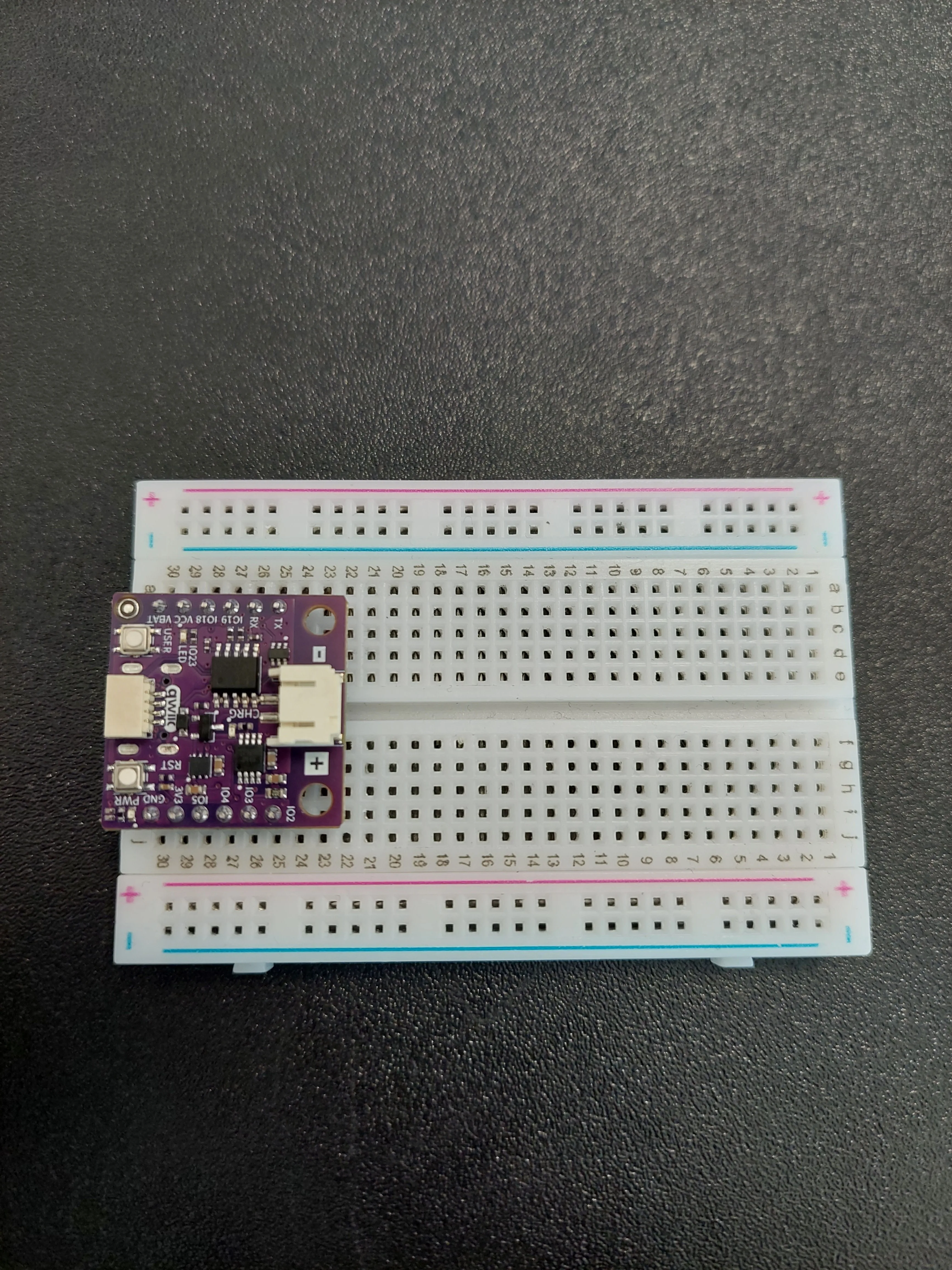
This example uses three pins. The names are printed along both edges of the board, and each pin sits in its own numbered row. In the photo the board occupies rows 25 to 30, which puts IO19 in row 27 on the a–e side, and IO4 in row 27 and GND in row 30 on the f–j side.
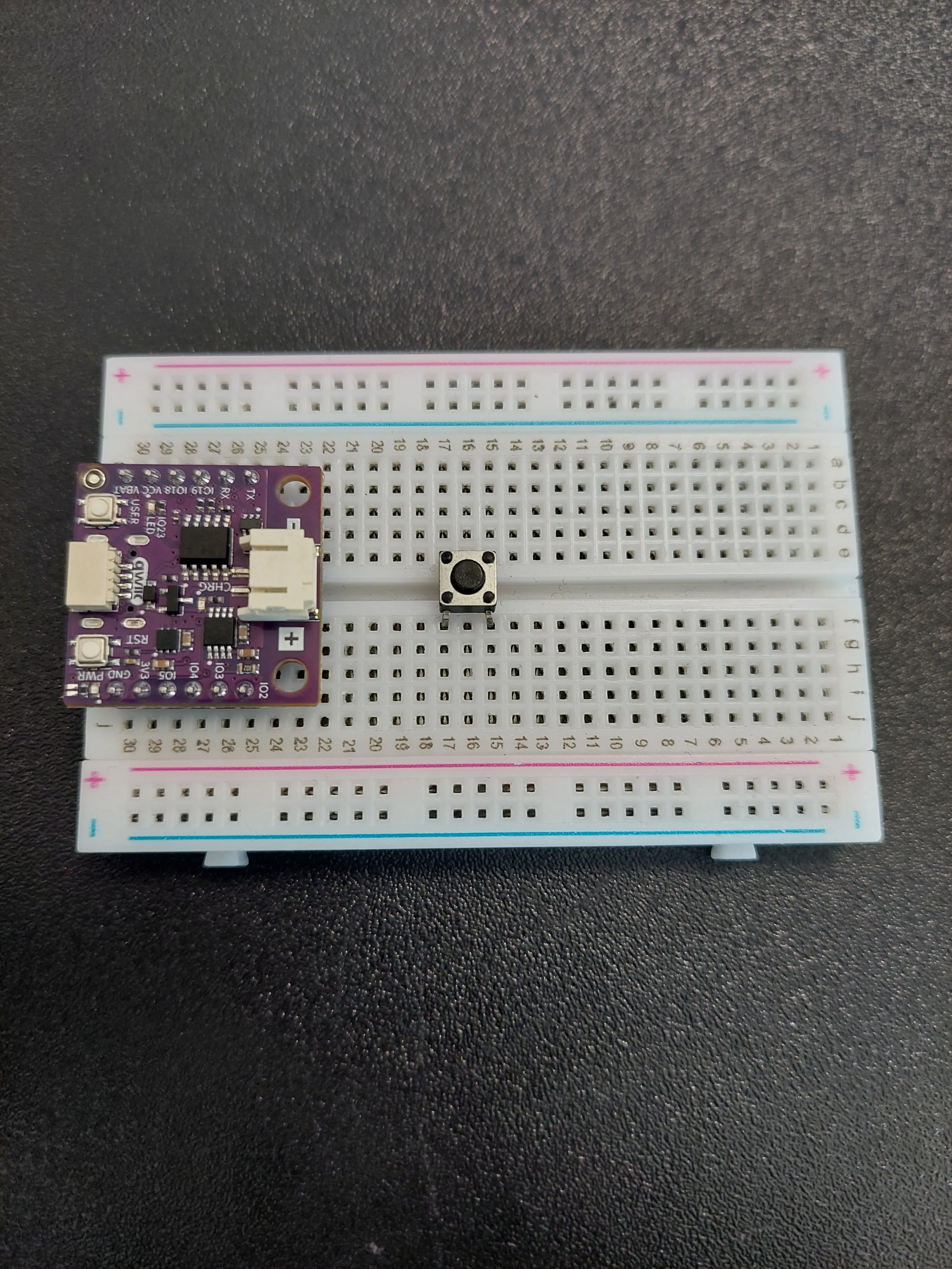
2. Place the push button
Push the button into the middle of the breadboard so that it straddles the centre channel, a few rows clear of the board. In the photo its legs are in rows 15 and 17.
3. Connect GND to the button
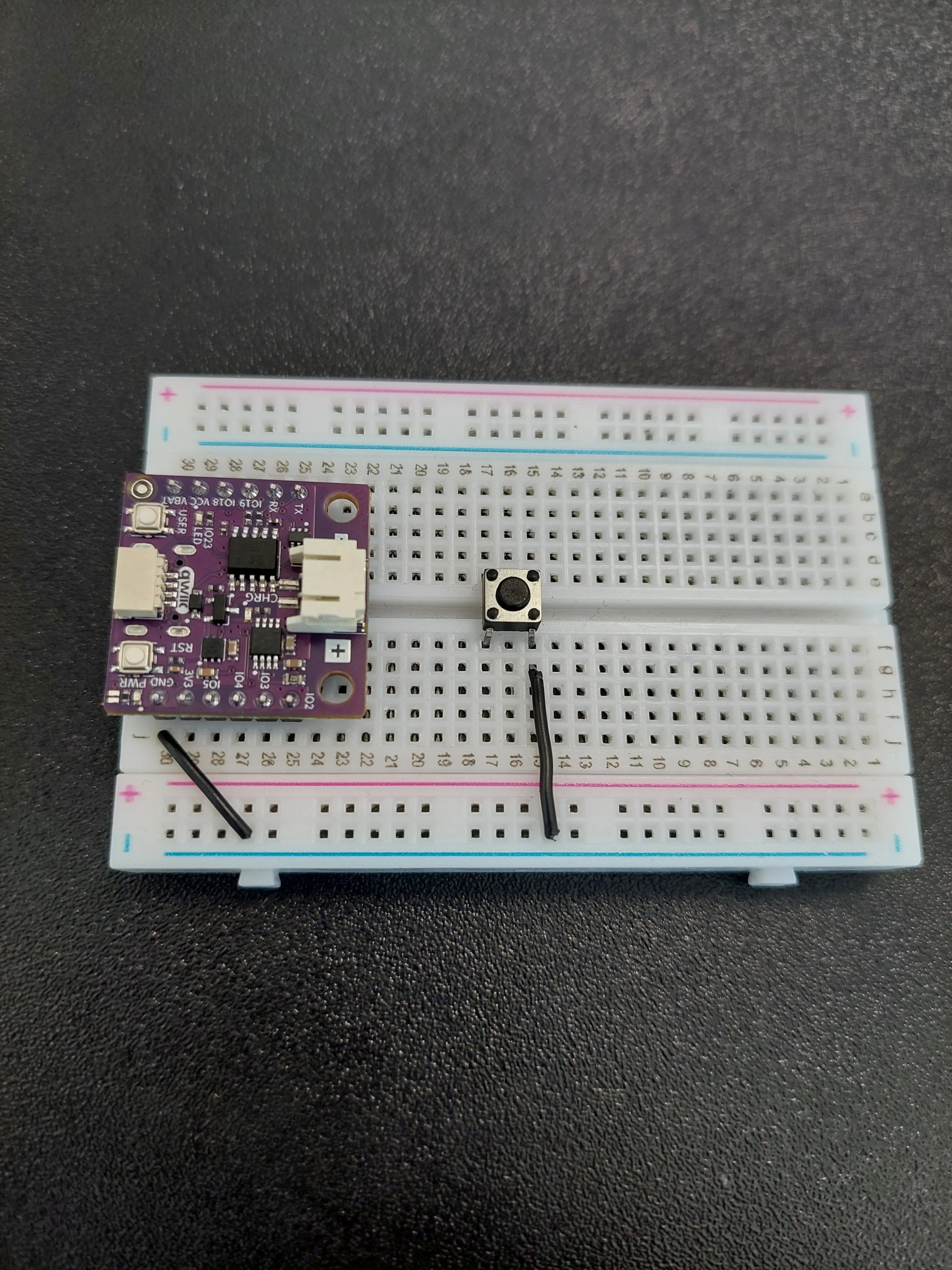
Ground goes across in two hops, using the blue − rail along the edge of the breadboard as a shared ground line.
- First jumper: from the row holding GND (row 30 in the photo) out to the blue − rail.
- Second jumper: from that same blue − rail back to row 15, on the f–j side of the button.
4. Connect IO19 to the button
Run a single jumper from the row holding IO19 (row 27 on the a–e side) to row 17, on the a–e side of the button.
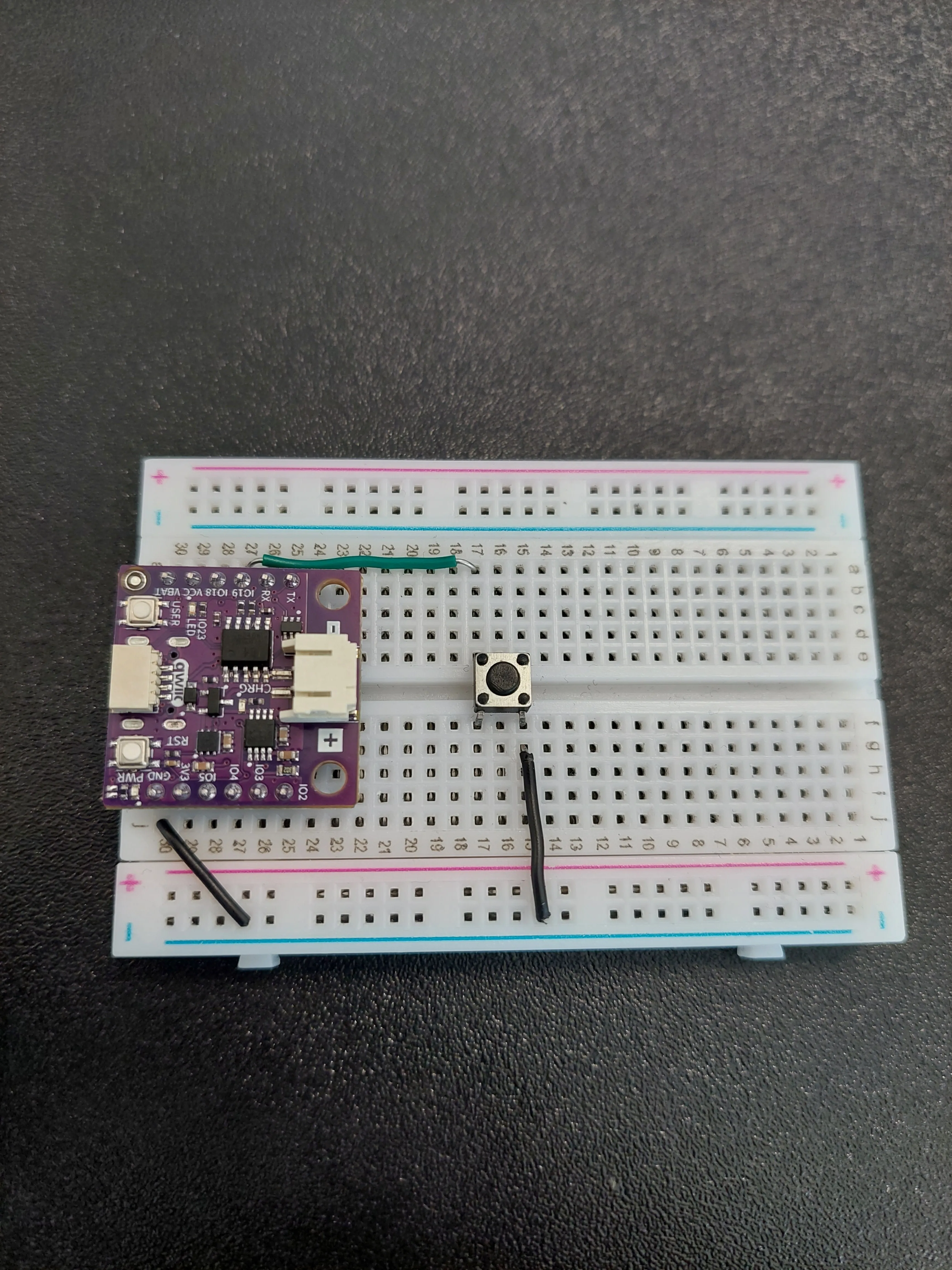
The two wires reach the button from opposite sides: row 15 on the f–j side, row 17 on the a–e side. That is the diagonal pair, and it is what makes the button actually switch something. The button is now finished; the rest of this page is the LED.
5. Bring IO4 out and add the resistor
The LED is driven by IO4, which sits in row 27 on the f–j side of the board, the same side as GND and the opposite side from IO19.
- The board covers most of that row, so use the outermost hole, j27, and run a jumper along to row 7.
- Then place the 330 Ω resistor so it bridges row 7 to row 5.
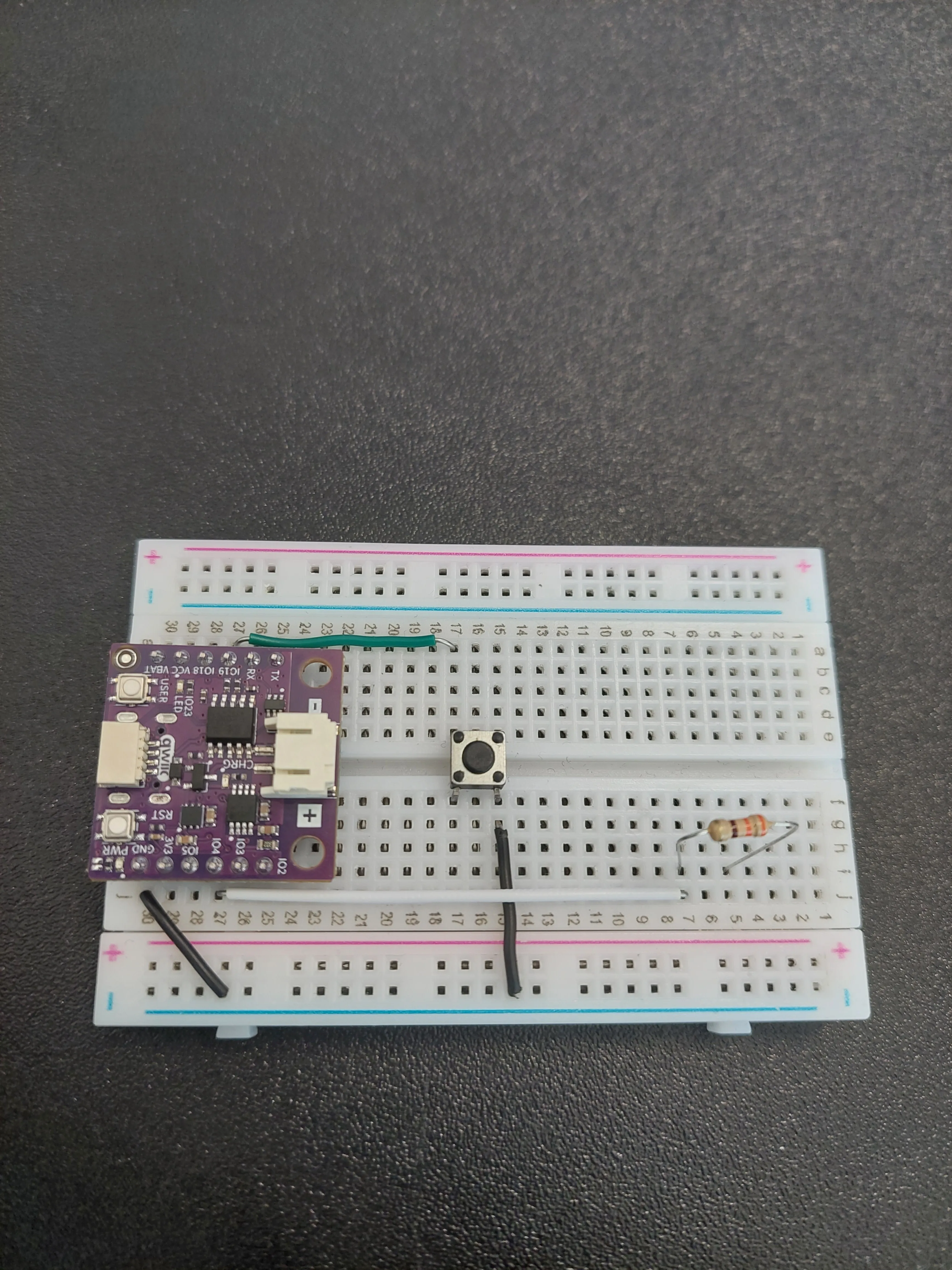
6. Add the LED
The LED goes in next, continuing the chain: long leg (anode) into row 5, the same row the resistor ends in, and short leg (cathode) into row 3.
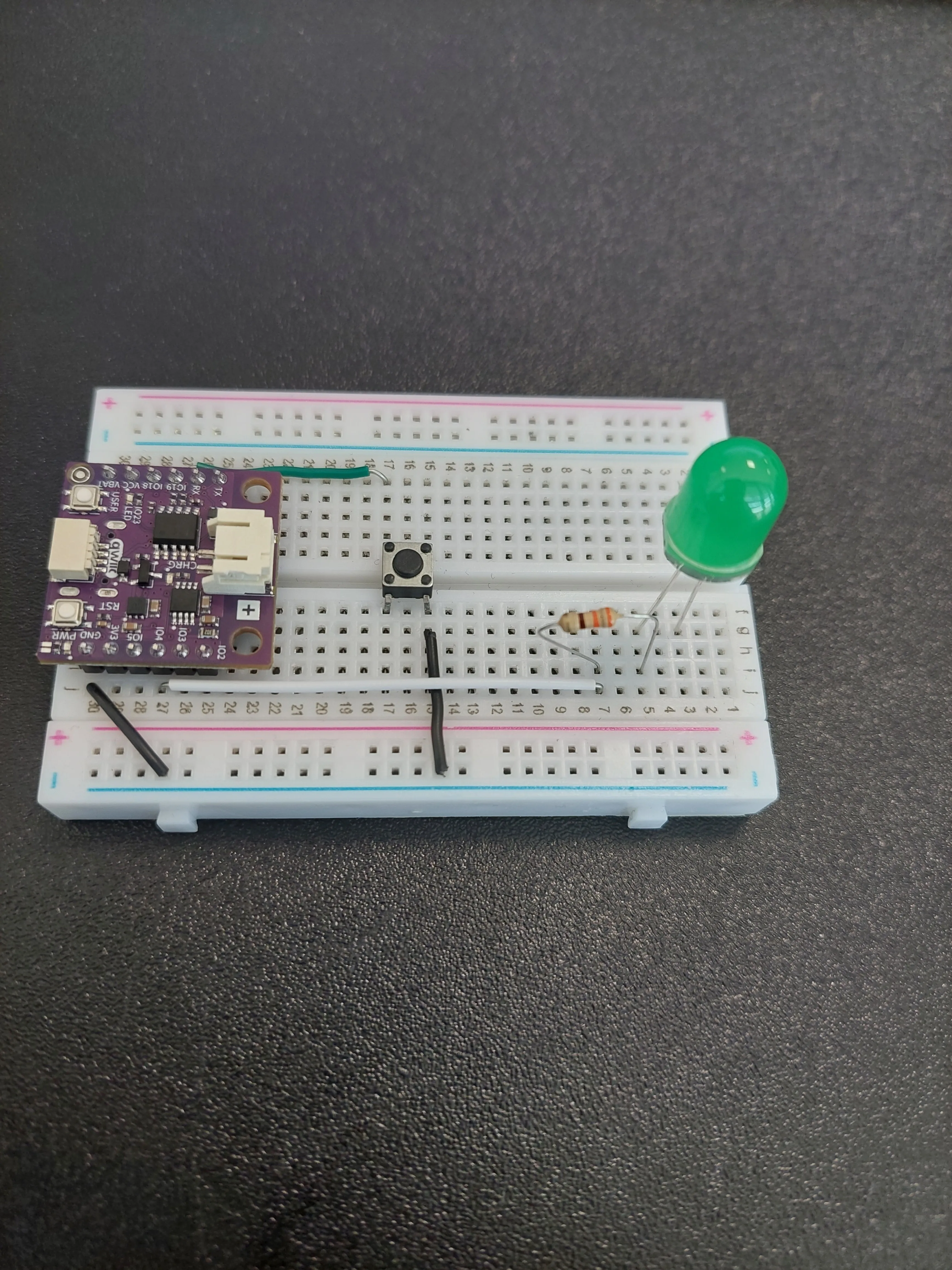
7. Connect the LED to ground
One jumper closes the circuit: from row 3, where the short leg of the LED sits, across to the blue − rail, the same rail the button already uses for ground.
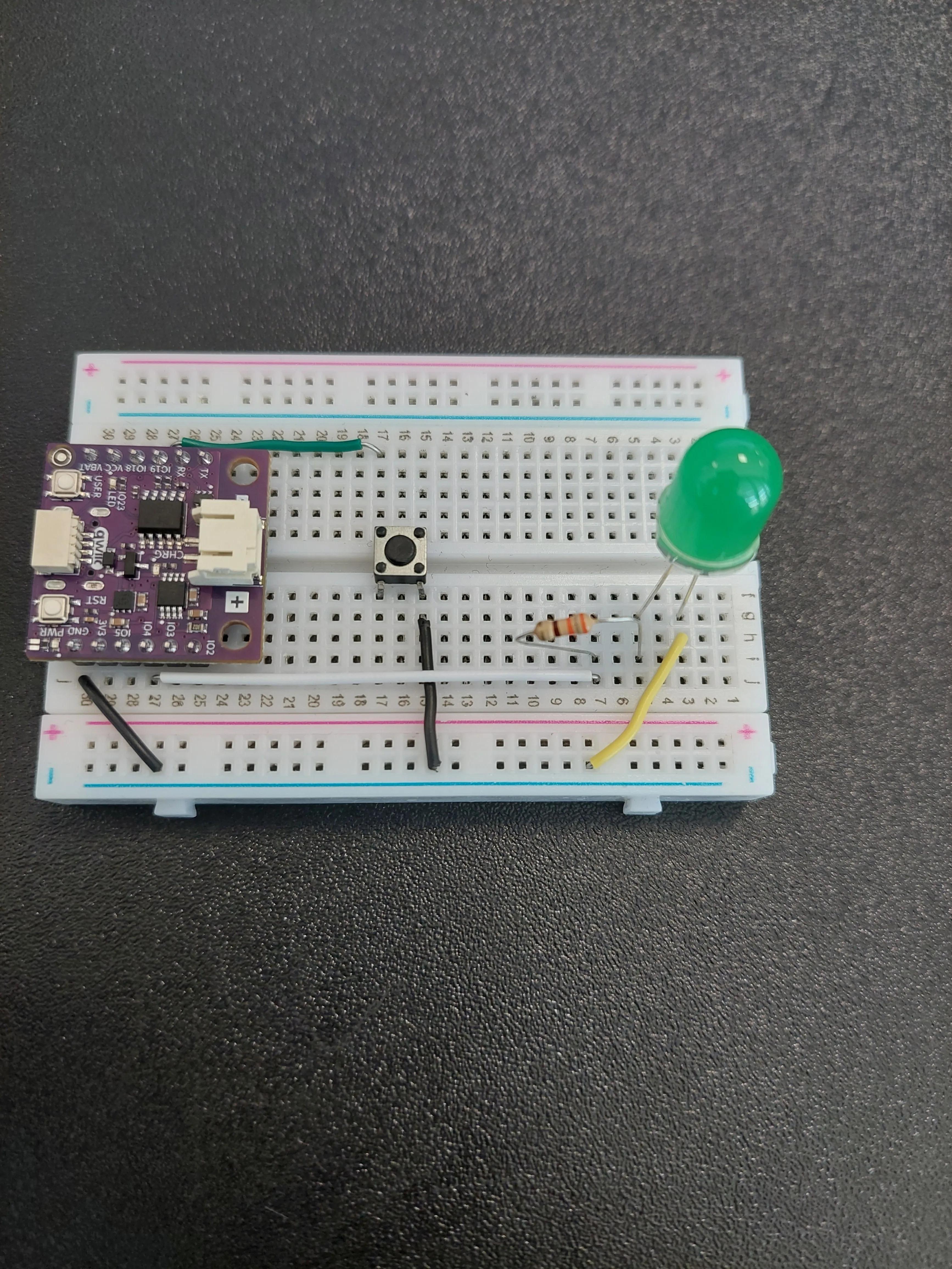
The full path is now IO4 → 330 Ω → LED → − rail → GND. Because the rail is shared, the button and the LED both take their ground from the same place.
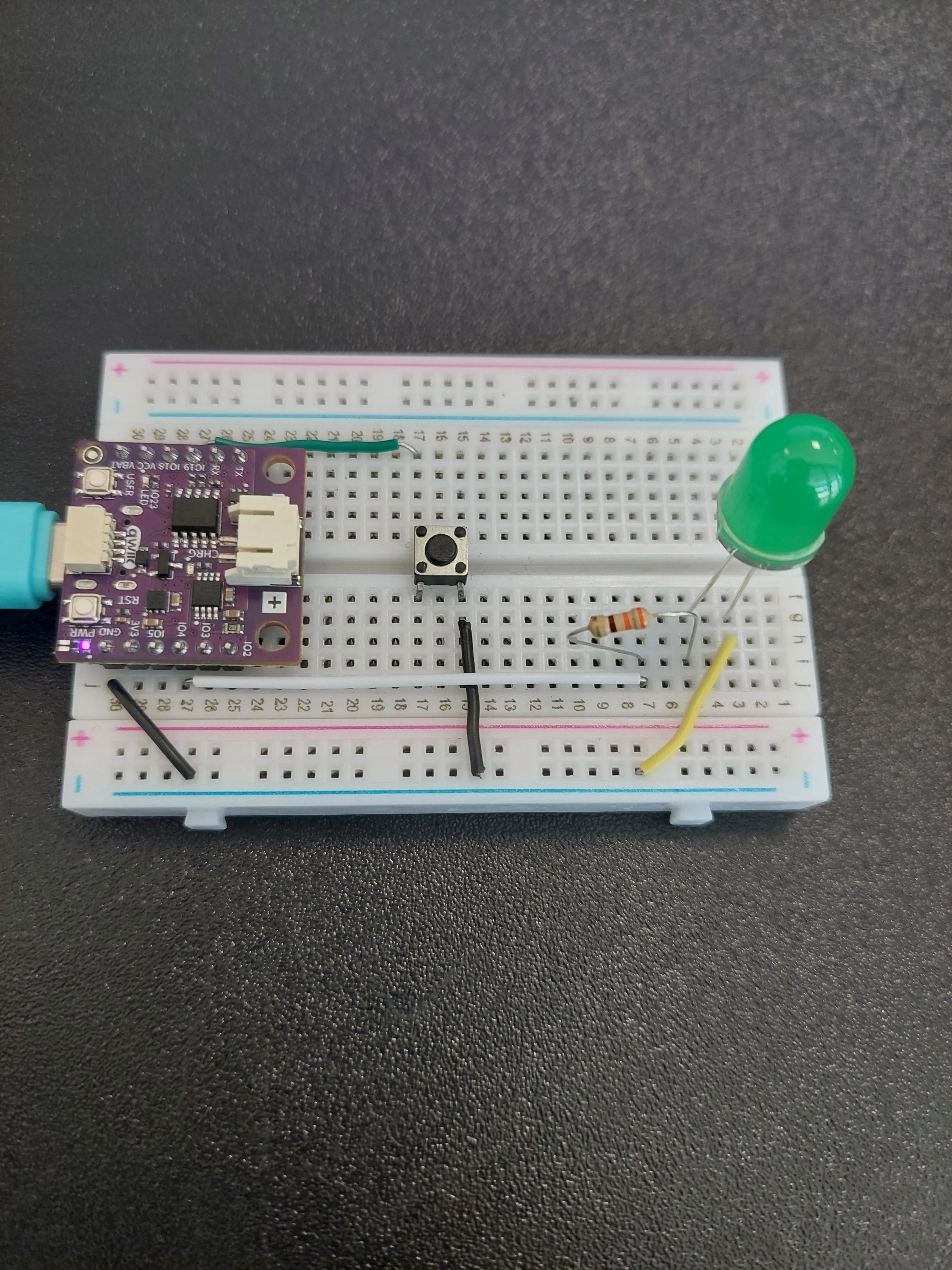
8. Connect the board to your computer
Creating the two pins
This example needs one pin in each direction, and both are created in the same place at the top of the file. The button reads, so it gets Pin.IN together with the Pin.PULL_UP you met in the previous example. The LED writes, so it gets Pin.OUT.
btn = Pin(BUTTON_PIN, Pin.IN, Pin.PULL_UP)
led = Pin(LED_PIN, Pin.OUT)
We also switch the LED off explicitly before the loop starts:
led.value(0)
False. If the pin happened to be left high by a previously running script, what you saw and what the program believed would disagree, and the first press would appear to do nothing.Reading the button state
value() reads the pin and returns either 1 (high) or 0 (low). We read it once per pass through the loop and keep the answer in a variable:
reading = btn.value()
Pin.PULL_UP switches on a resistor inside the chip that holds the pin at 3.3 V, so the pin reads 1 while the button is released. Pressing the button connects the pin to GND, so it reads 0. A button wired this way is called active low, and it is why the code below watches for a change from 1 to 0.Button debouncing
When you press a button, it changes from an open circuit to a closed circuit, which we treat as a single press. For us it feels like one clean action, because we react slowly compared to electronics. But to a microcontroller, which checks the button state thousands of times in that short moment, it looks very different.
As the button is pushed, two metal contacts inside touch each other. Since they are not perfectly smooth or aligned, they can quickly connect and disconnect a few times before settling. To the microcontroller, that looks like the button was pressed several times in a row, even though you only pressed it once.
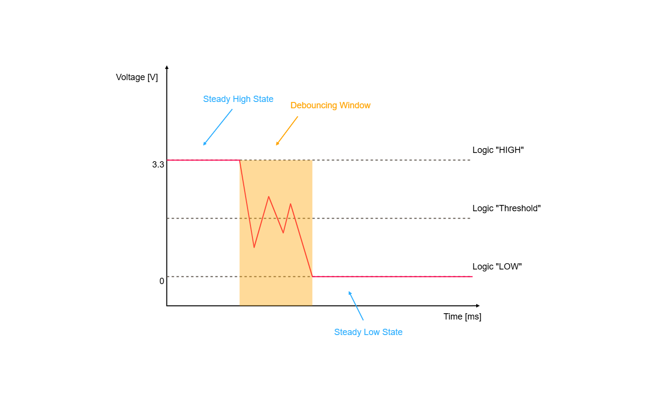
The simplest software-based strategy to handle this is the delay-based debouncer. The whole point of it is to wait out the bouncing window, and to do that we need to know how much time has passed.
time.ticks_ms() returns a counter of milliseconds that the board keeps while it is powered on. Comparing two of those readings tells us how long ago something happened, so we can ignore any change that arrives too soon after the last one.
now = time.ticks_ms()

if reading != last_state and time.ticks_diff(now, last_change_ms) > DEBOUNCE_MS:
    last_change_ms = now
time.ticks_diff(), never by subtracting them. The counter returned by time.ticks_ms() does not grow forever. It reaches a limit and wraps back around to a small number. When that happens, now - last_change_ms gives a large negative answer and the debouncer stops working until the board is restarted. time.ticks_diff(now, last_change_ms) knows about the wraparound and returns the real difference. This is the one place where MicroPython is stricter than the Arduino millis() you may be used to.Toggling the LED
Each time a valid press is detected we flip the state of the LED. This code sits inside the debouncer, so it only runs for presses that survived the filter.
if last_state == 1 and reading == 0:

    # We toggle the led_state. The "not" operator flips True into False and False into True.
    led_state = not led_state

    # We turn the LED on or off depending on the current led_state.
    if led_state:
        led.value(1)
    else:
        led.value(0)

    print("Button pressed, toggling LED")

last_state = reading
last_state == 1 and reading == 0 is what makes this fire once per press rather than once per release. It is only true at the exact moment the reading changes from released to pressed, which is called the falling edge. Letting go of the button changes the reading back from 0 to 1, which the debouncer sees but this condition ignores.Code
Below is the full example code for toggling an LED with a debounced button.
from machine import Pin
import time

# This is a variable to which we pass the number of pin that we had connected the BUTTON to.
# The NULA board has a pin naming logic as follows: IO19, where 19 is the number that we give to the variable.
BUTTON_PIN = 19

# This is a variable to which we pass the number of pin that we had connected the LED to.
# Remember that the LED needs a 330 Ohm resistor in series with it. That resistor limits how much current flows,
# and without it the LED draws more than either it or the pin is built for, so both can be damaged.
LED_PIN = 4

# Here we create our two Pin objects. The button is set to Pin.IN because we read it, with Pin.PULL_UP switching
# on a resistor inside the chip that ties the pin to 3.3V while the button is released. The LED is set to
# Pin.OUT because we write to it.
btn = Pin(BUTTON_PIN, Pin.IN, Pin.PULL_UP)
led = Pin(LED_PIN, Pin.OUT)

# Those are the variables used for button debouncing.
# "led_state" remembers whether the LED is currently on, "last_state" remembers what the button read the last time
# we looked, and "last_change_ms" remembers when that reading last changed.
led_state = False
last_state = 1
last_change_ms = 0
DEBOUNCE_MS = 25

# Make sure the LED starts out switched off, so the state we remember matches what you actually see.
led.value(0)

while True:

    # value() is a function that reads the value from our pin, either 1 (high) or 0 (low).
    reading = btn.value()

    # time.ticks_ms() returns the number of milliseconds passed since the board was powered on. This counter
    # eventually wraps around back to zero, which is why we never compare two of these numbers directly and
    # always use time.ticks_diff() to work out the difference between them.
    now = time.ticks_ms()

    # This is our debouncing logic: we check if the button reading has changed and if enough time has passed so
    # that we do not get false readings because of the noise in the signal.
    if reading != last_state and time.ticks_diff(now, last_change_ms) > DEBOUNCE_MS:
        last_change_ms = now

        # As we are using the pull-up method for reading the button, the readings are the other way around from
        # what you might expect: the pin reads high while the button is released and low while it is pressed.
        # So we need to toggle the LED when the button state goes from high to low.
        if last_state == 1 and reading == 0:

            # We toggle the led_state. The "not" operator flips True into False and False into True.
            led_state = not led_state

            # We turn the LED on or off depending on the current led_state.
            if led_state:
                led.value(1)
            else:
                led.value(0)

            print("Button pressed, toggling LED")

        last_state = reading

    # A very short pause leaves the processor a moment to handle its own background work.
    time.sleep_ms(10)
What you should see
Press Run. Nothing happens at first. The LED starts off. Press the button once and it turns on, press it again and it turns off. Each accepted press also prints a line to the Shell, so you can see the debouncer working:
Button pressed, toggling LED
Button pressed, toggling LED
Button pressed, toggling LED
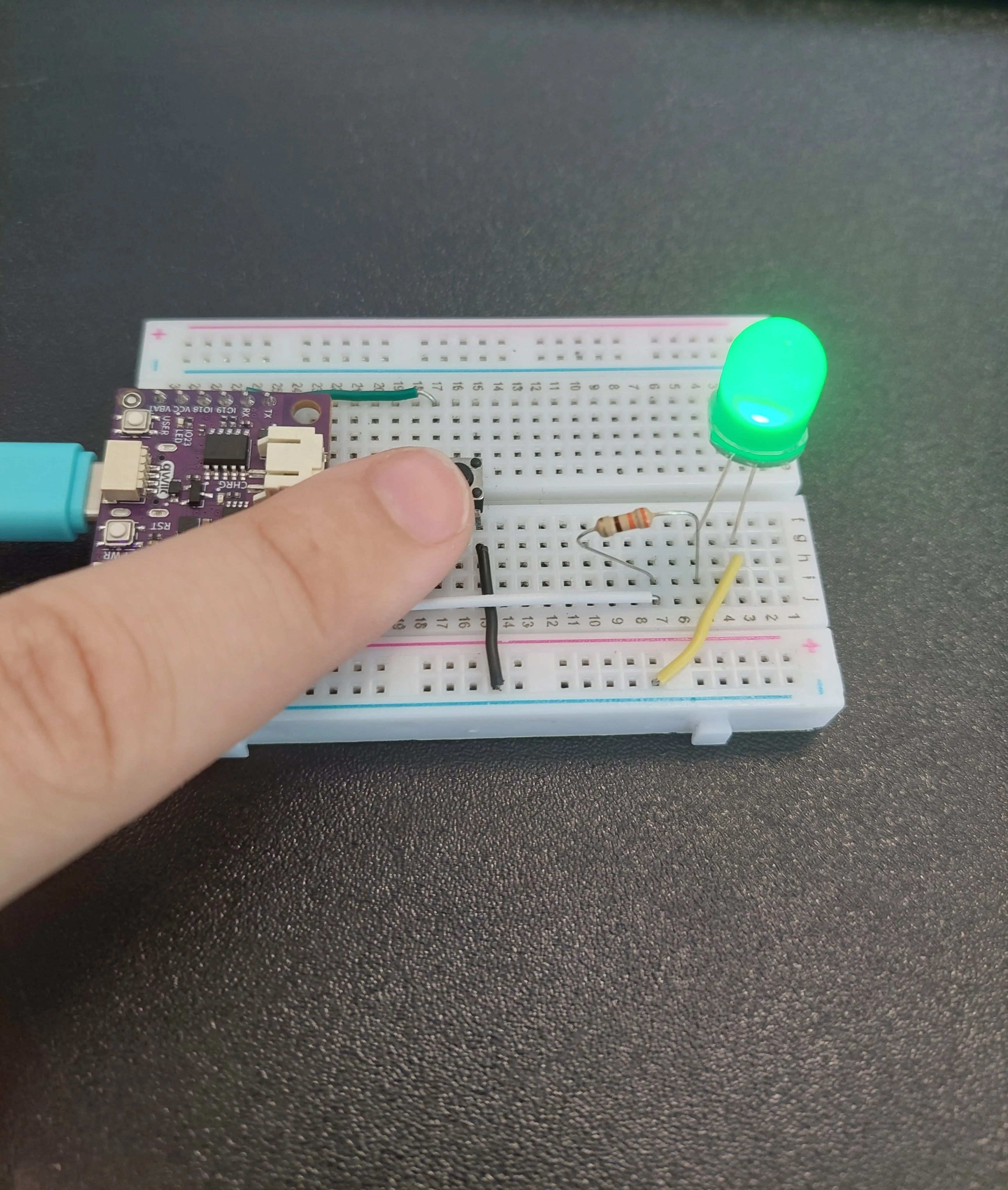
last_state == 1 and reading == 0 doing its job, not the debouncer: it is only true on the single pass where the reading changes from released to pressed. What the debouncer adds over 2.1 Button Counter is that it never blocks. 2.1 waits in a loop for you to let go, so the board can do nothing else while the button is held down; this version reads the button, decides and carries on, which is what any program with other work to do actually needs.Full example
Check out the full example code on the link below:
2.2_Button_Debounce.py
Example that toggles an LED with a debounced button press.