4.1 LCD Message Display
Every example so far has reported back through the console, which means the board only has something to say while it is tethered to a computer. This one changes that: the 16x2 LCD in the kit gives the board a screen of its own, and a message printed there stays on it whether the computer is watching or not.
The wiring is the easiest in the whole kit. The LCD is a Qwiic module, so one cable does everything.
In this documentation you will learn:
- How to connect the 16x2 LCD with a single Qwiic cable.
- What the purple I2C LCD adapter on the back of the display is for.
- How to initialize a display and turn on its backlight, and why the order matters.
- How to put text where you want it with
setCursor(), and why counting from zero matters. - Why only 16 characters fit on a row, and what happens to the seventeenth.
- What to do when the screen glows but stays empty, the one fault that catches everybody.
Hardware required:
- 1x Soldered NULA MINI board
- 1x Breadboard
- 1x 16x2 LCD display with I2C adapter
- 1x Qwiic cable
- 1x USB-C cable
Putting the components together
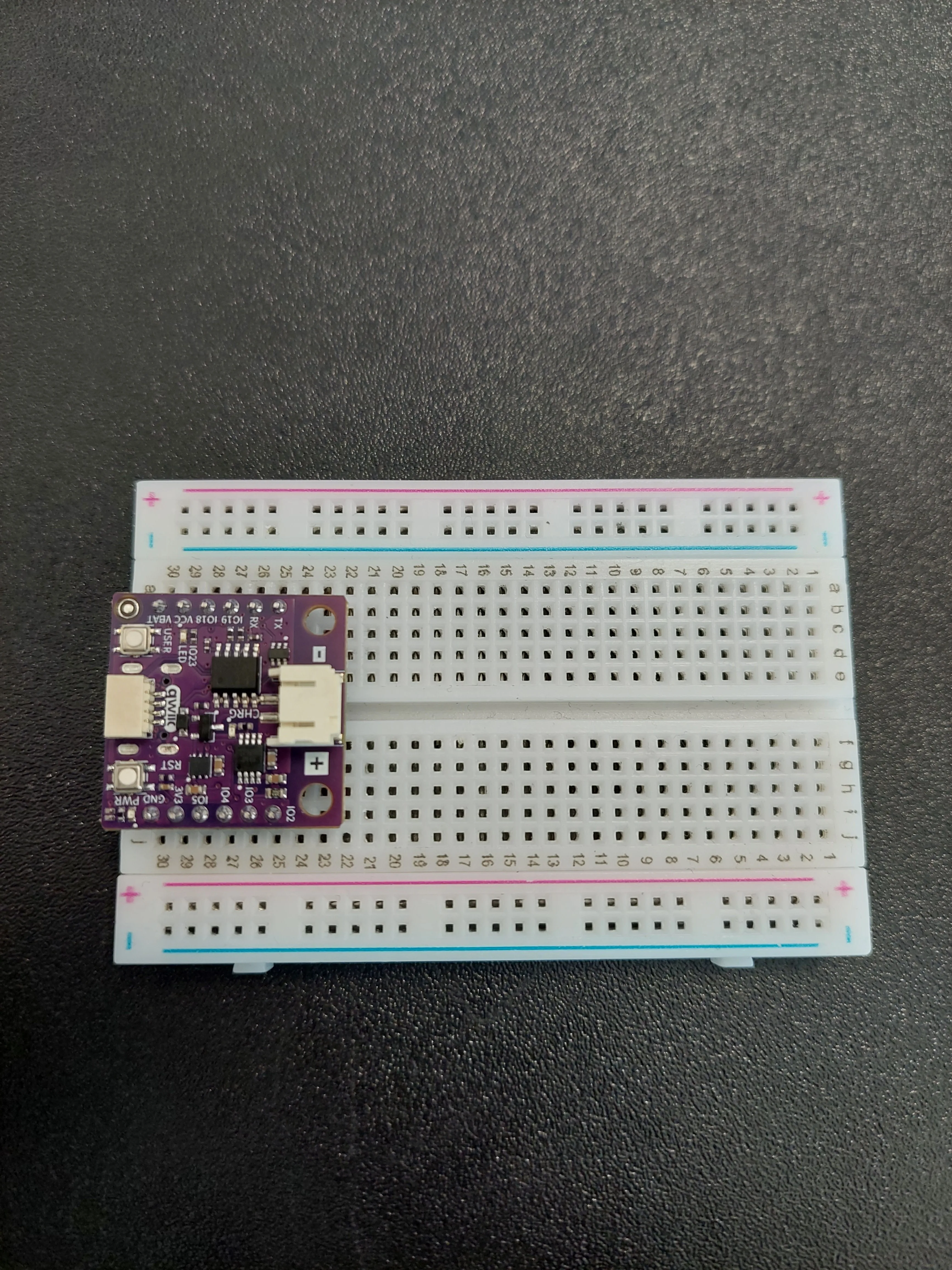
1. Insert the NULA MINI board on the breadboard
Push the board into one end of the breadboard so that its two rows of pins sit on either side of the centre channel, with the chip facing down.
2. Plug the Qwiic cable into the board
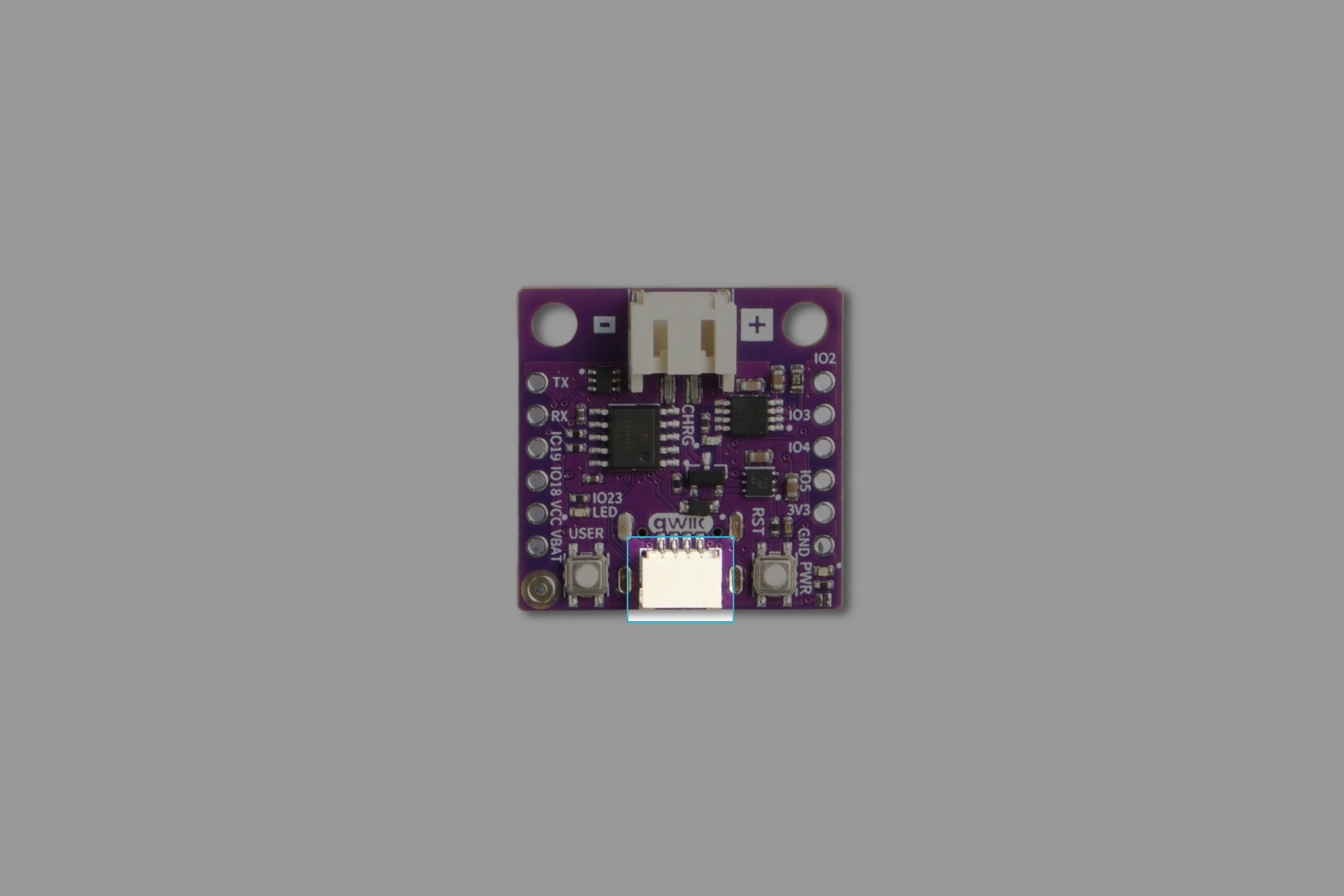
The NULA MINI has one Qwiic connector, on the edge of the board between the USER and RST buttons. It is the white connector marked qwiic on the silkscreen. Push the cable in until it clicks.
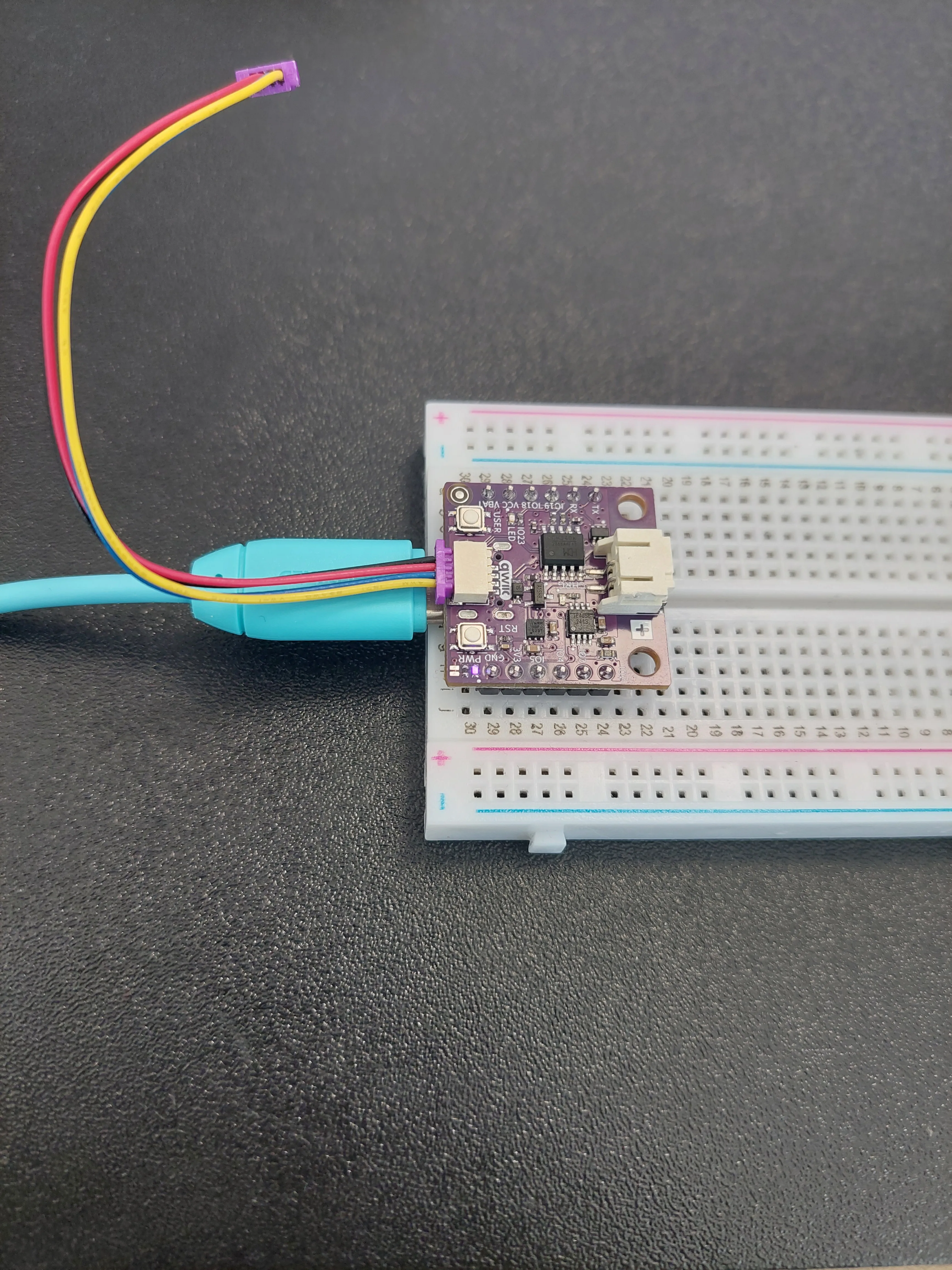
- and +. That one is the battery connector, and a Qwiic cable will not fit it.If you would like to see exactly which connector this is on a bare board, it is highlighted here:
3. Plug the other end into the display
Turn the display over and you will find a purple board screwed to its back, silkscreened I2C LCD ADAPTER. It carries two Qwiic connectors, one at each end. Plug the free end of the cable into either one. They are wired together, and the spare exists so you can chain another module onwards.
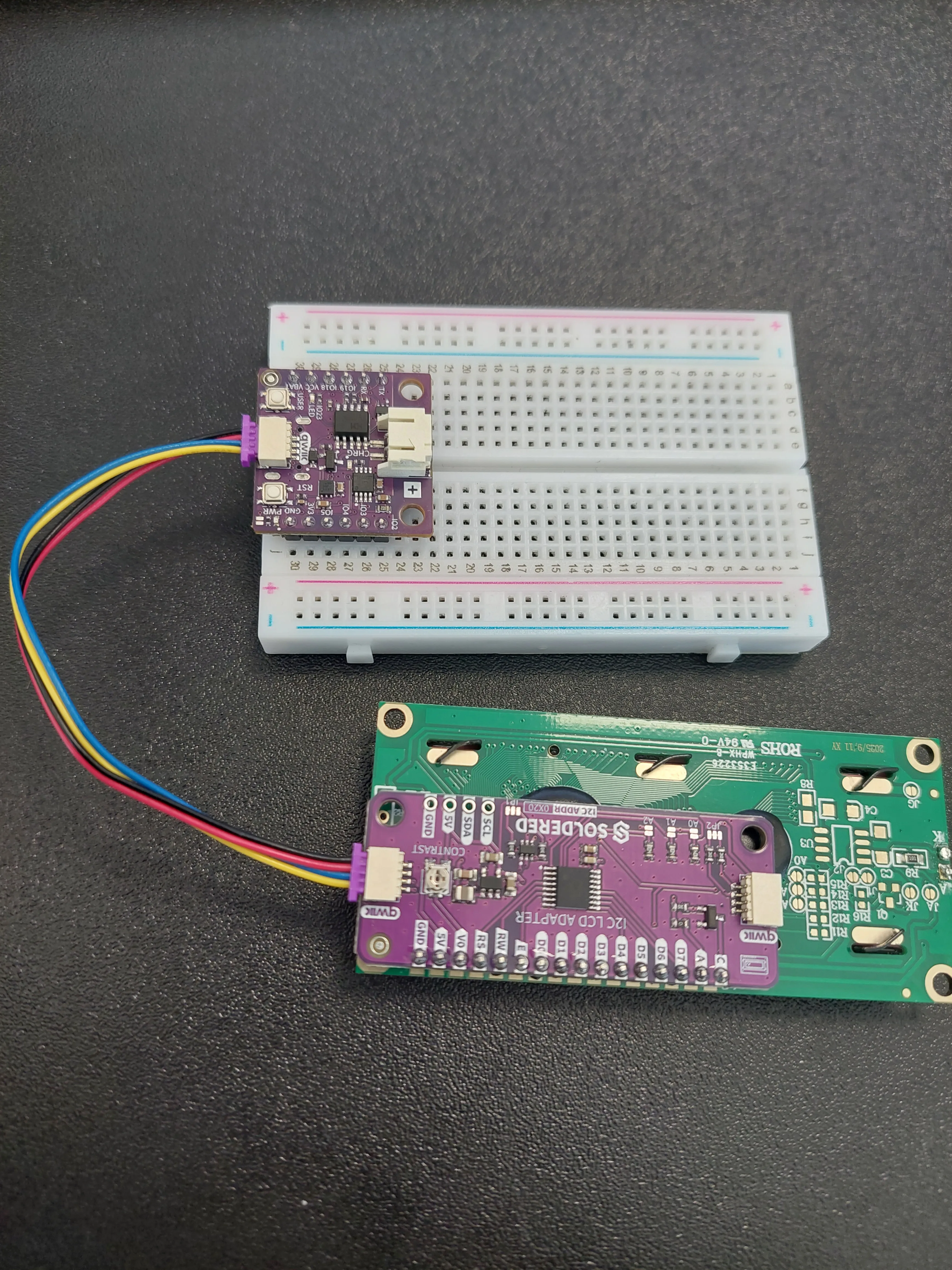
SCL, SDA, 5V and GND. That is the same connection brought out to solder pins, for boards that have no Qwiic socket. You do not need it here. The cable does the same job.4. Plug in the USB-C cable
Connect the board to your computer. The purple PWR light comes on and the backlight of the display lights up blue, but the screen itself stays empty, because nothing has told it what to show yet.
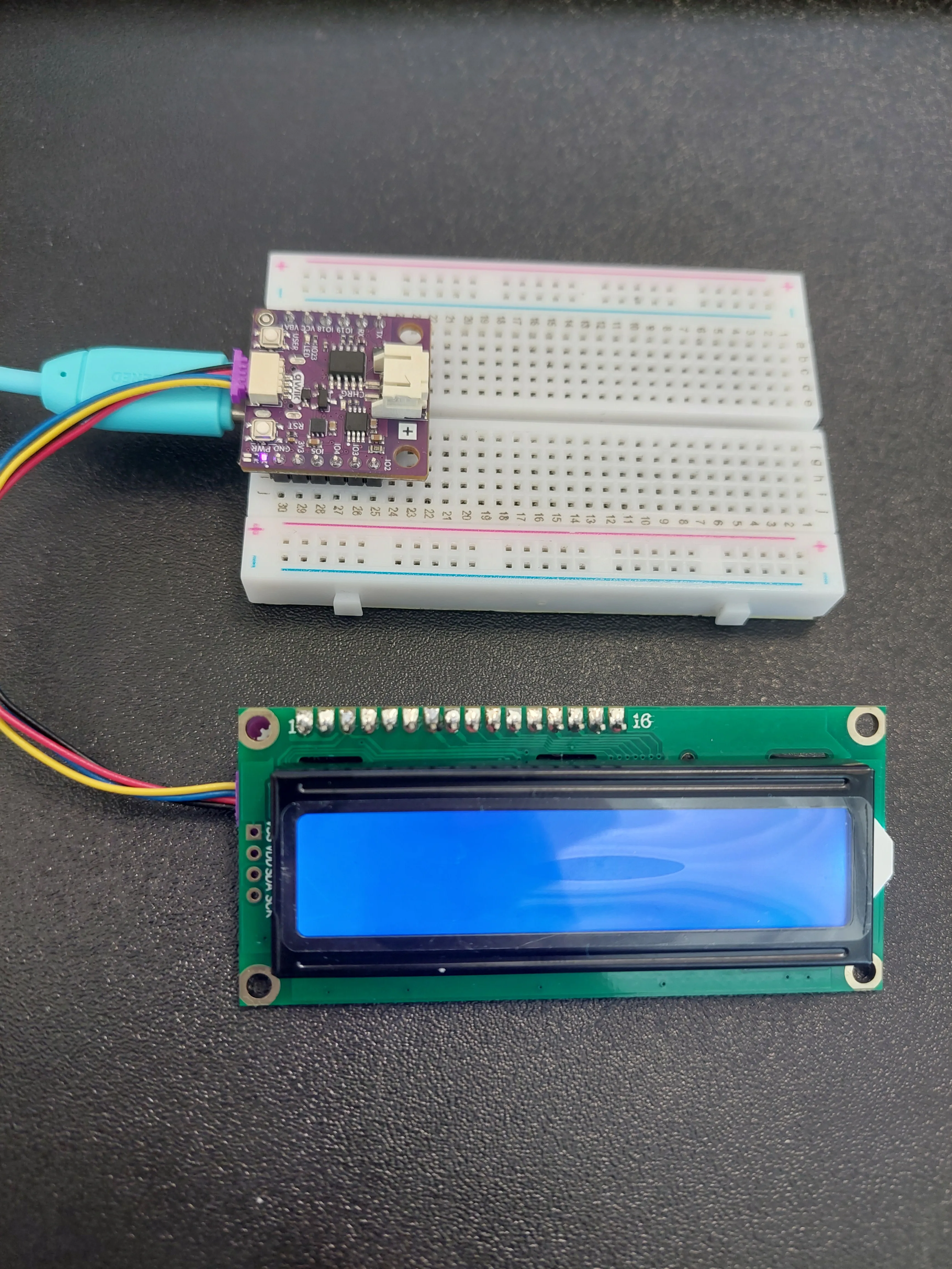
What the adapter board is for
Look closely at the green display board and you will count 16 pins along its top edge, labelled VSS, VDD, V0, RS, RW, E, D0 through D7, A and K. That is the native interface of the HD44780, the controller chip that has driven displays like this since the 1980s. Wiring it directly means fourteen or so connections, and you would spend this whole example pushing jumper wires into a breadboard.
The purple adapter board does that job for you. It sits on those 16 pins permanently and talks to your board over just two wires instead.
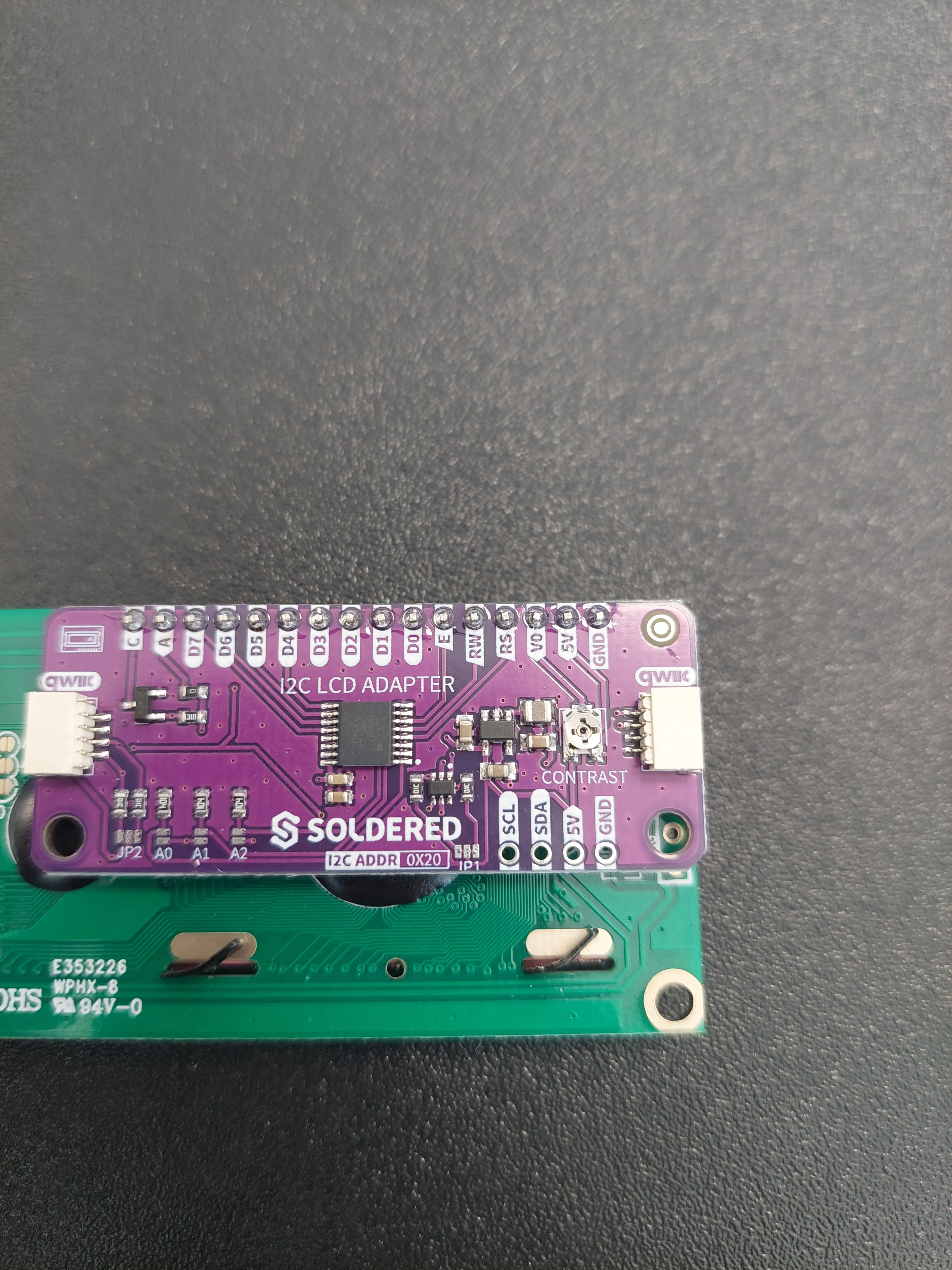
Those two wires are the I2C bus, the same one the ultrasonic sensor used in example 3.1: SDA carries the data and SCL provides the clock that keeps both ends in step. Several modules can share one pair of wires, each answering to its own address, which is why this board has I2C ADDR 0X20 printed on it. 0x20 is the number this display answers to.
That is why the display is created from the same i2c object you already know, with no address and no pin numbers of its own:
i2c = I2C(0, scl=Pin(7), sda=Pin(6))
lcd = LCD_I2C(i2c)
LCD_I2C already knows that 0x20 is where to find the display, and it sets the controller up for a two-row screen on its own, unlike the Arduino library, which is created as LCD lcd(16, 2). There is nothing to pass but the connection.scl=Pin(7), sda=Pin(6) part is not optional, exactly as in 3.1. Swap the two numbers or leave them out and the display never answers, which looks like a dead screen but is a mistyped pin.You may also spot three small pads marked A0, A1 and A2 near the SOLDERED logo. Bridging them with solder changes the address, up to 0x27. You would only ever do that to put two of these displays on one cable. Leave them alone.
Getting the driver onto the board
This example needs LCD.py, which lives in the lib folder of the examples repository. As with the ultrasonic sensor, the driver has to be on the board itself, in its /lib folder, which is where MicroPython looks when it sees from LCD import LCD_I2C.
If you followed Setting up MicroPython all four drivers are already there. If not:
mpremote mip install github:SolderedElectronics/Soldered-NULA-Beginner-kit-MicroPython-project-examples/lib
ImportError: no module named 'LCD' means the driver is not on the board, or it landed somewhere other than /lib. There is nothing wrong with the wiring or the display.begin() before backlight()
Two calls start the display, and their order is not interchangeable:
lcd.begin()
lcd.backlight()
begin() opens the conversation and prepares the display for use. It also resets the display as part of that, which switches the backlight off. So backlight() has to come second. Put it first and the light goes out again a moment later, leaving you with a dark screen and no obvious reason why.
clear() then wipes anything left over from whatever ran before. Without it you can end up reading a mixture of an old message and a new one, because the display keeps showing whatever it was last told until something changes it.Rows, columns, and counting from zero
The display is a grid: 16 characters across, 2 rows down. lcd.setCursor(column, row) chooses where the next thing you print will land, and both numbers start at zero:
lcd.setCursor(0, 0)is the very first character of the top row.lcd.setCursor(0, 1)is the very first character of the bottom row.
So the rows are numbered 0 and 1, not 1 and 2, and the columns run 0 to 15. Getting that wrong does not raise an error, which is what makes it hard to spot: the driver treats every row other than 0 as the bottom row, so setCursor(0, 2) and even setCursor(0, 5) all quietly write to row 1. If a line of text keeps landing on the wrong row, this is why.
The 16-character limit is worth taking seriously, because the display does not wrap onto the next row. Print a nineteen-character string and you see the first sixteen characters and nothing more. The last three are not lost, though. Each row is really a 40-character buffer inside the controller chip, and the glass is only a 16-character window onto it, so the extra characters sit just off the edge of the screen. Example 4.2 puts that to work by sliding the window along. For now the practical rule is simply that anything past the sixteenth character will not be visible. Both messages in this example are twelve characters long, so both fit comfortably:
column: 0123456789012345
row 0:  Hello, NULA!
row 1:  Let's start!
Everything happens once
One last thing to notice before the code: this script has no while True loop at all. It runs from the first line to the last and then ends.
That is deliberate. An LCD holds whatever it was last told to show, without being reminded, so printing the message once is enough. It stays on the screen after the script has finished, and only disappears when you cut the power or run something else.
setup() and leaves loop() empty for the same reason. MicroPython does not need the empty loop at all. A script that reaches its last line has simply finished.Code
# I2C is a way for several devices to talk to the board over just two wires, and it is what the Qwiic connector
# carries. We need it here because the display is a Qwiic module.
from machine import I2C, Pin

# The Soldered driver for the LCD display. It lives in the lib folder of the examples repository, so copy the whole
# lib folder onto your board, otherwise MicroPython will not be able to find it.
from LCD import LCD_I2C

# Here we set up the I2C connection. The two pins are fixed by the board: on the NULA MINI, I2C uses IO6 for the
# data line (SDA) and IO7 for the clock line (SCL), which are exactly the pins the Qwiic connector is wired to.
i2c = I2C(0, scl=Pin(7), sda=Pin(6))

# Here we create our display object, which we named "lcd", and hand it the I2C connection.
# The display in this kit is 16 characters wide and 2 rows tall, which is where the name 16x2 comes from.
lcd = LCD_I2C(i2c)

# begin() starts the communication and prepares the display for use. It has to come first, before anything else we
# ask the display to do.
lcd.begin()

# backlight() turns on the light behind the screen, without which the text is very hard to read. Note that this has
# to come after begin(), because begin() resets the display and would switch the light back off.
lcd.backlight()

# clear() wipes anything that was left on the screen from before, so we start from a clean display.
lcd.clear()

# setCursor() chooses where the next text will appear. The first number is the column and the second is the row, and
# both start counting at zero, so (0, 0) is the top left corner.
# print() then writes our text starting at that position.
lcd.setCursor(0, 0)
lcd.print("Hello, NULA!")

# Move to the second line and print another message. (0, 1) means column zero of row one.
# Keep in mind that this display fits exactly 16 characters per row, so anything longer is cut off at the edge.
lcd.setCursor(0, 1)
lcd.print("Let's start!")

# And that is all. Unlike the earlier examples there is no while True loop here, because nothing needs to happen
# over and over: the message stays on the screen until the board is reset or powered off.
What you should see
Press Run. Within a second both lines appear, the same build as the photo above, now with something on the screen:
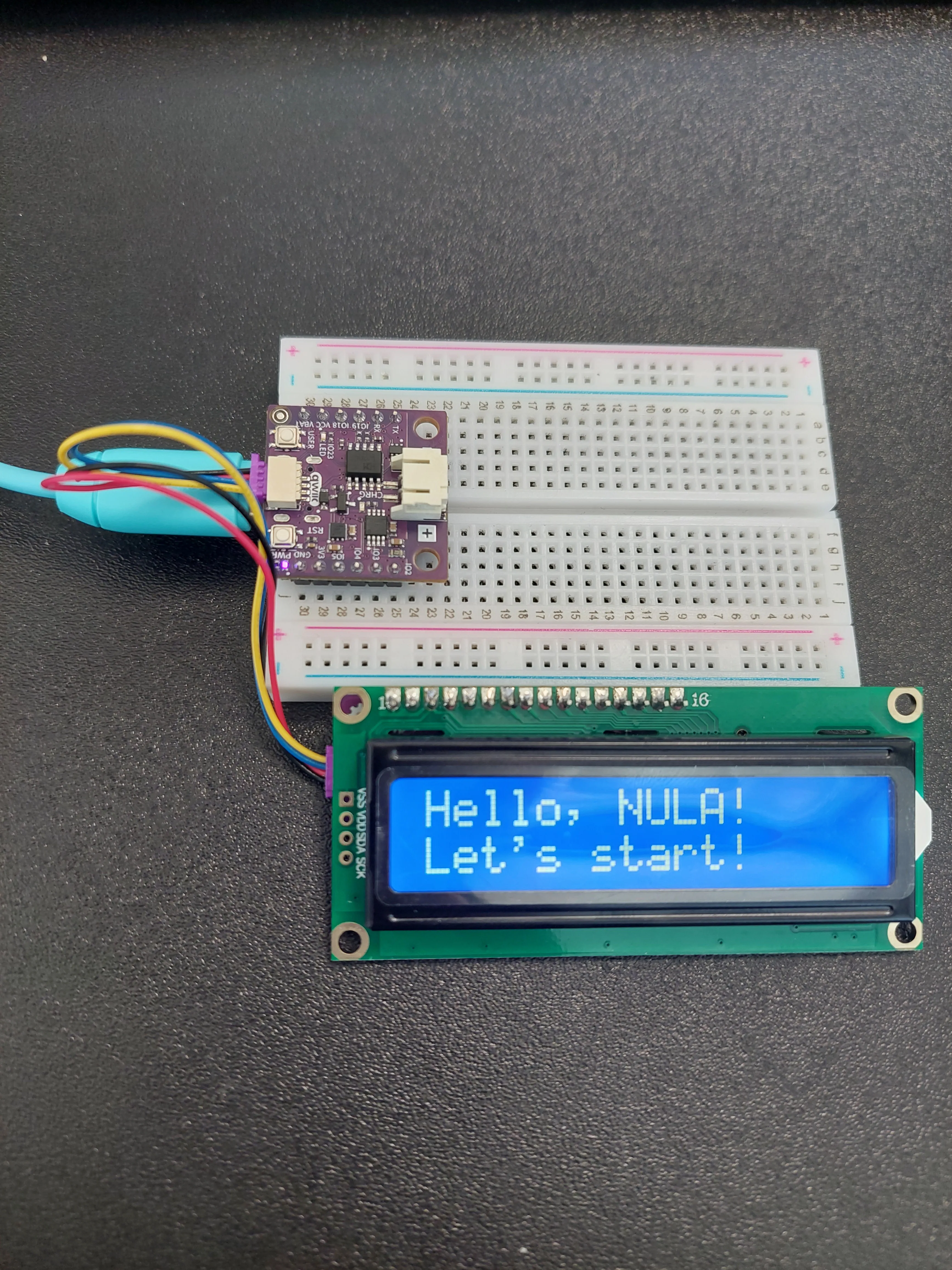
Nothing is printed to the Shell this time. The script never calls print() on its own, because the display is the output. Note that lcd.print() and the built-in print() are two different things: one writes to the screen, the other to the console.
If the backlight is on but the screen is empty
This is the single most common problem with these displays, and it is not a fault in your code.
The characters are being sent correctly, but the contrast voltage of the display is set so low that they are invisible against the backlight. The fix is a small trimmer potentiometer on the adapter board, marked CONTRAST:
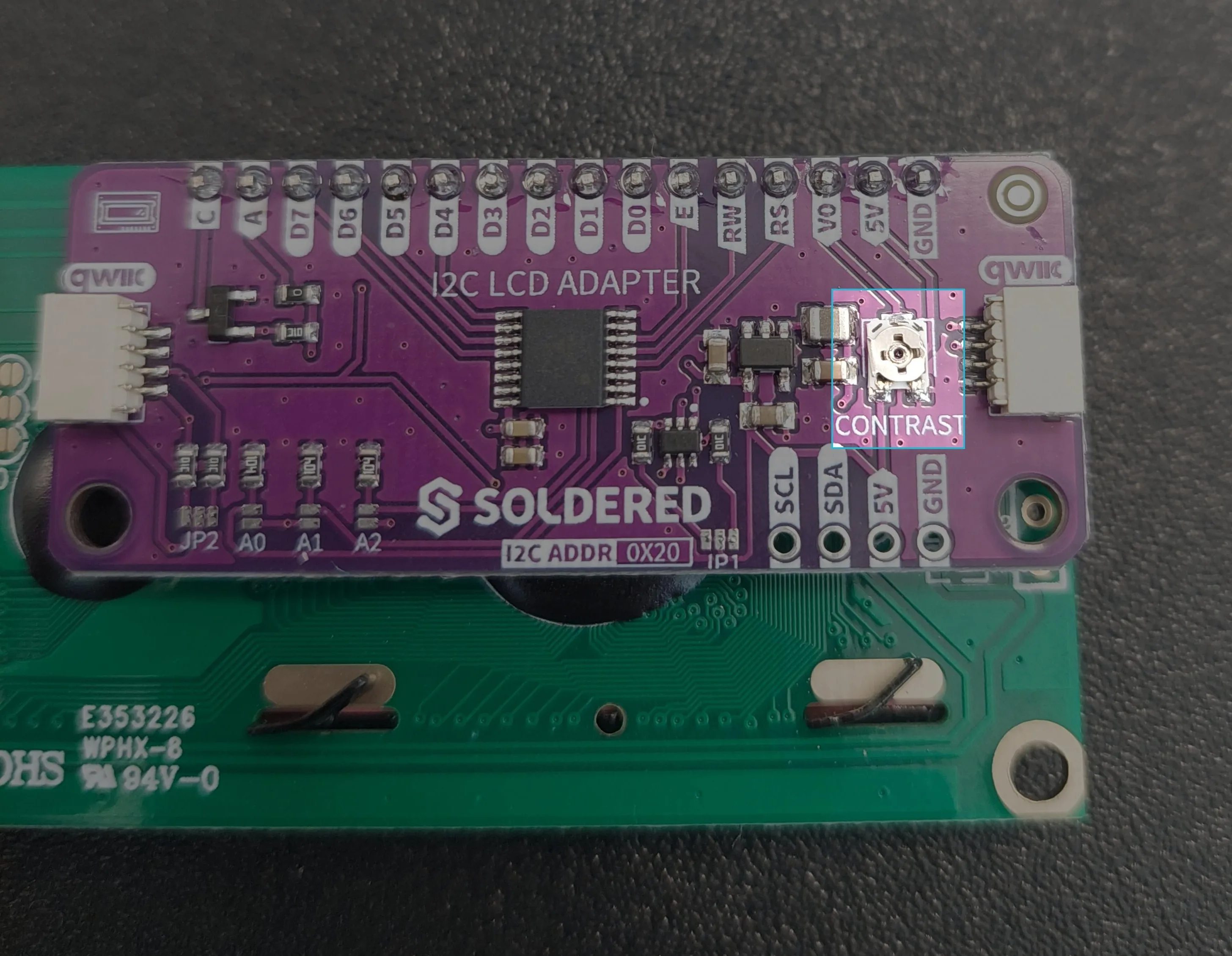
With the board powered and the script run, turn that trimmer slowly through its full range with a small flat screwdriver. At one end you get a blank blue screen; at the other, a row of solid dark blocks. Your text is somewhere in between. Stop where the characters look crisp. You only ever need to do this once.
scl=Pin(7), sda=Pin(6) in the I2C() line, then reseat both ends of the Qwiic cable until each one clicks. A script that stops with OSError: [Errno 19] ENODEV never reached the display at all.Try it yourself: change one of the messages to something longer than sixteen characters and run it again. You will see it clipped at exactly the sixteenth character, which is a quicker way to learn the limit than counting.
Full example
Check out the full example code on the link below:
4.1_Print_Message.py
Example that initializes the Qwiic 16x2 LCD and prints a static two-line message using the Soldered LCD driver.