5.1 Temperature and Humidity
The goal of this example is to measure the temperature and the humidity of the room with the SHTC3 sensor in the kit, and print both to the console. One chip the size of a grain of rice measures both at once, accurately enough that you will see the numbers move when you breathe on it.
This is the second Qwiic module in the kit, after the ultrasonic sensor in section 3. That means the wiring is again a single cable, and again there is nothing to get wrong.
In this documentation you will learn:
- How one sensor measures both temperature and relative humidity.
- What relative humidity is a percentage of, and why that matters.
- How to connect a second kind of Qwiic module, and why it needs no pin numbers of its own.
- Why one reading takes two function calls, and what happens if you skip the first.
- How
time.ticks_ms()paces the measurements without ever freezing the board.
Hardware required:
- 1x Soldered NULA MINI board
- 1x Breadboard
- 1x Soldered SHTC3 temperature and humidity sensor
- 1x Qwiic cable
- 1x USB-C cable
Putting the components together
Four steps, and only one of them is a connection.
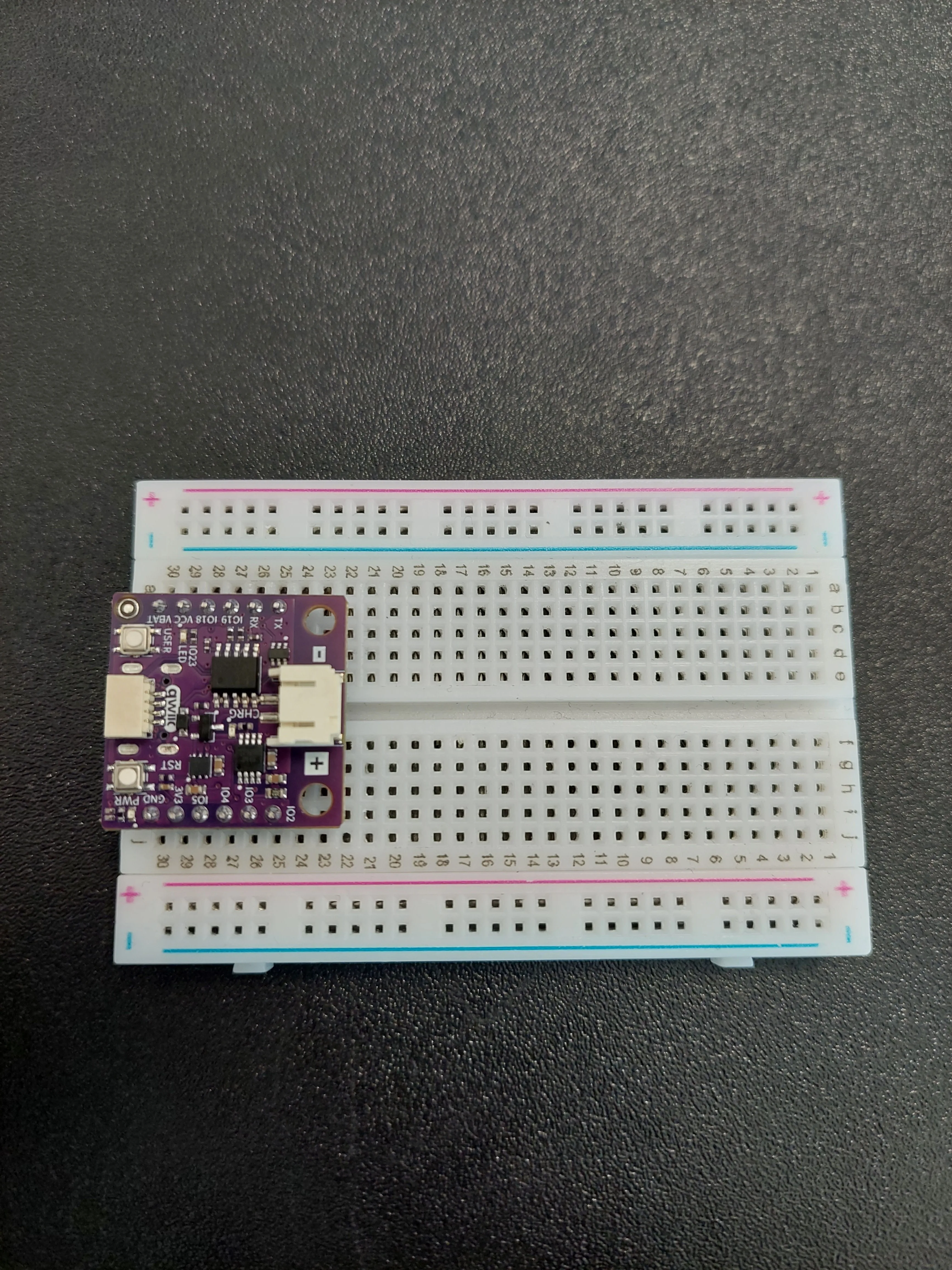
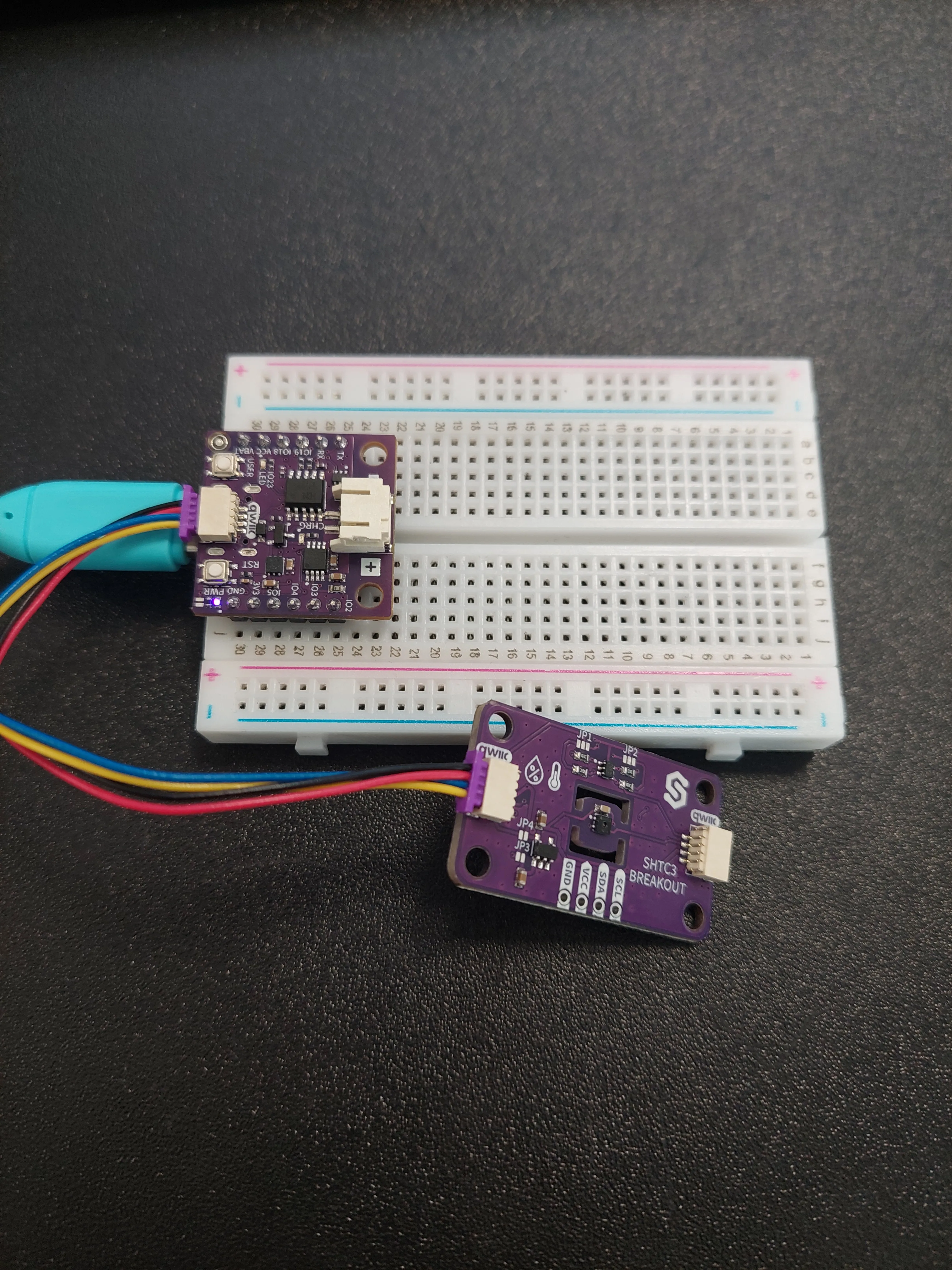
1. Insert the NULA MINI board on the breadboard
Push the board into one end of the breadboard so that its two rows of pins sit on either side of the centre channel. In the photos it occupies rows 25 to 30.
2. Plug the Qwiic cable into the board
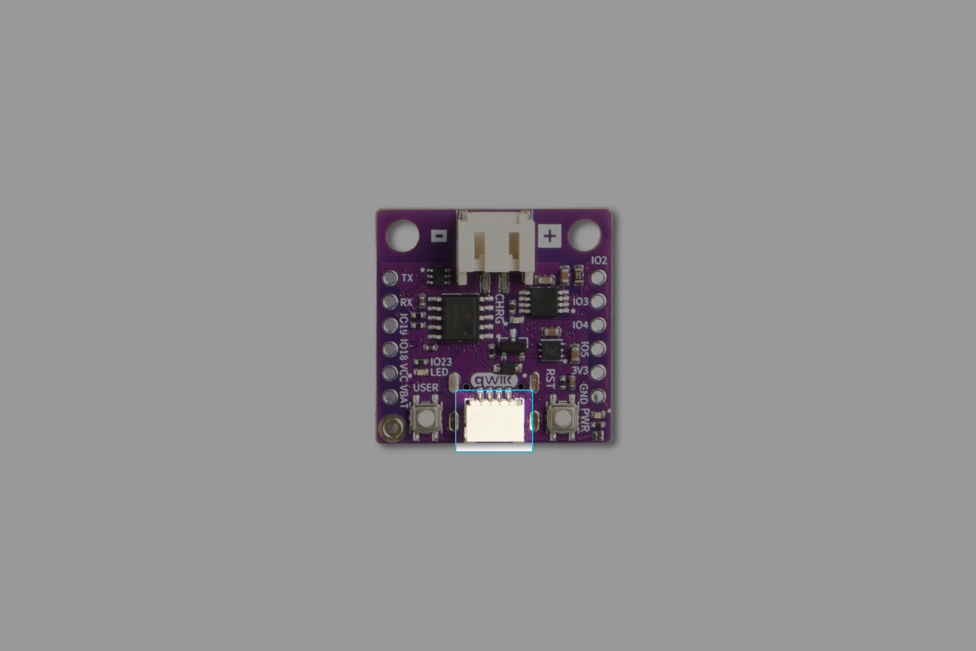
The NULA MINI has one Qwiic connector, on the edge of the board between the USER and RST buttons, marked qwiic on the silkscreen. Push the cable in until it clicks.
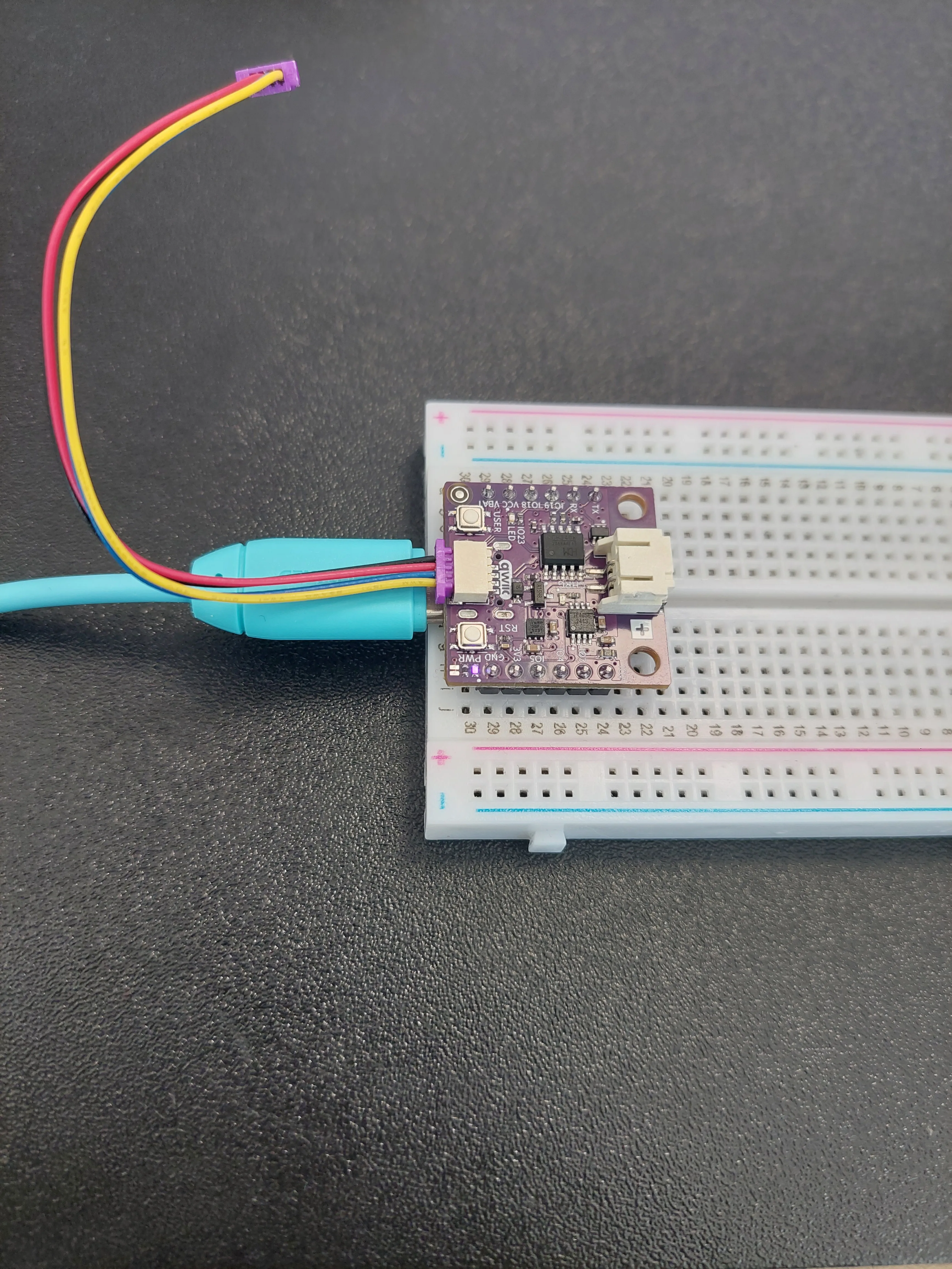
- and +. That one is the battery connector, and a Qwiic cable will not fit it.If you would like to see exactly which connector this is on a bare board, it is highlighted here:
3. Plug the other end into the sensor
The sensor is a small purple board silkscreened SHTC3 BREAKOUT. It has two Qwiic connectors, one at each end, with the word qwiic printed beside both. They are wired together, so plug the free end of the cable into either one. The spare is there so you can chain a further module onwards.
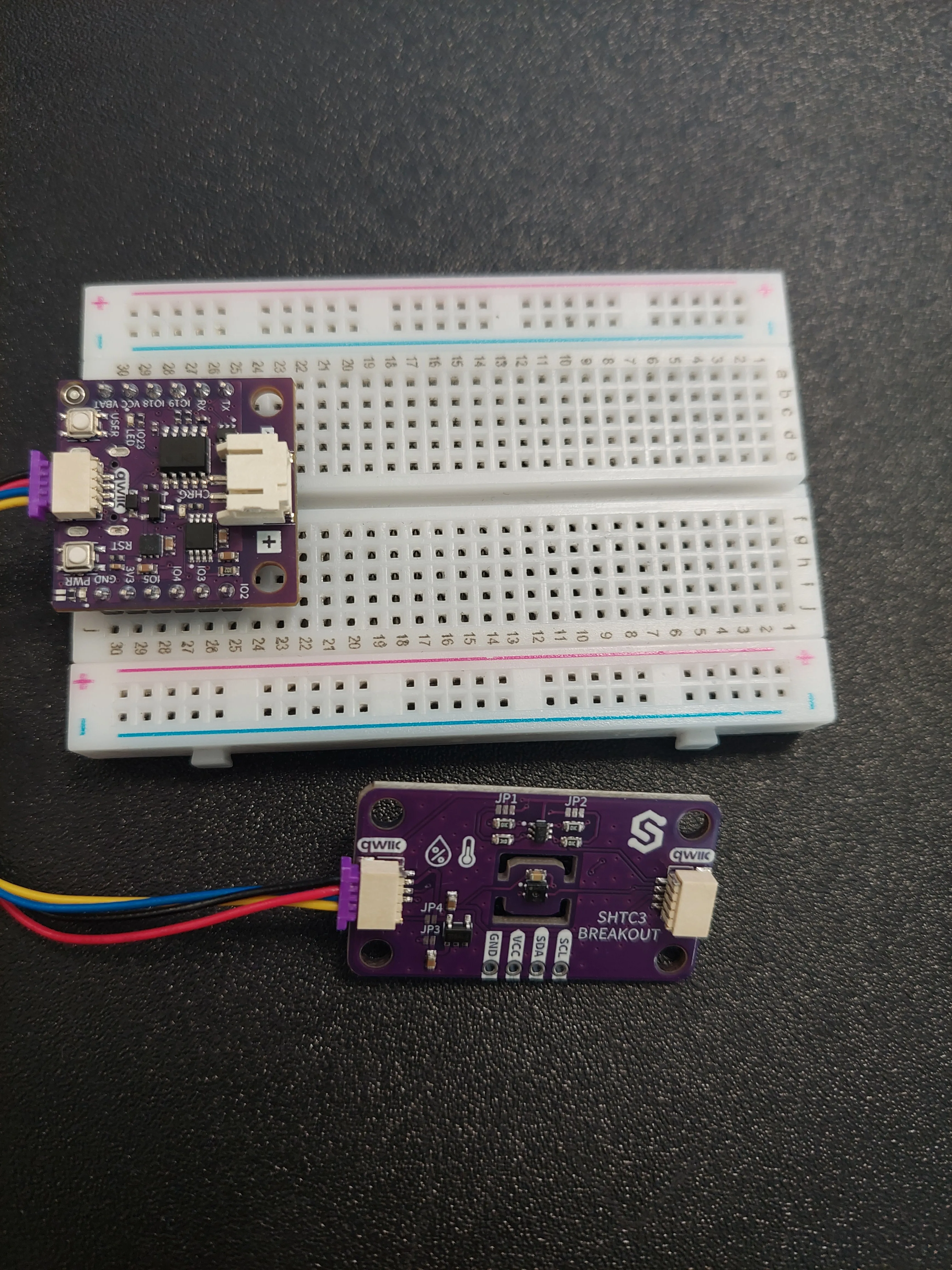
Here is the sensor board on its own, close up:
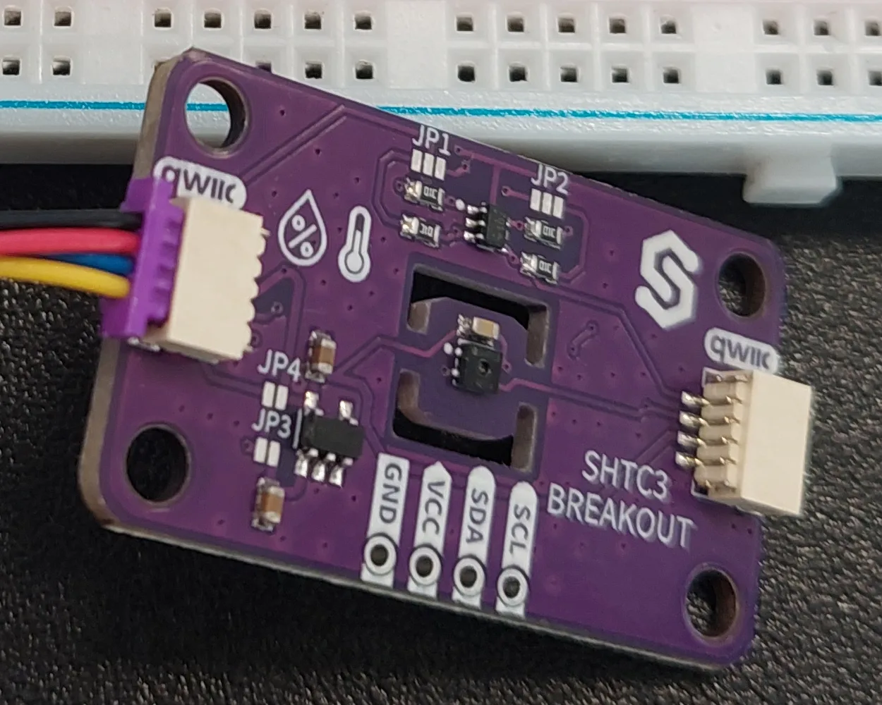
Worth noticing on this board:
- The sensor itself is the tiny black component in the middle. Both the thermometer and the humidity icon on the silkscreen point at it, because it really does measure both.
- It sits on a narrow tongue of circuit board with slots cut on either side of it. Those slots are deliberate: they make it harder for warmth from the rest of the board to travel along the copper and reach the sensor, which would otherwise report the temperature of the board rather than of the room.
- The four pads marked
SCL,SDA,VCCandGNDcarry the same four signals as the Qwiic cable, brought out for anyone who would rather solder wires than plug a cable in. You do not need them here. - The
JP1toJP4pads are factory settings. Leave them as they came.
4. Connect the USB-C cable
Plug the USB-C cable into the board and into your computer. The purple PWR light beside the RST button comes on, and the sensor is powered too, taking what it needs through the Qwiic cable.
What the sensor actually measures
Temperature is the straightforward half, reported in degrees Celsius.
Relative humidity is the half that catches people out. It is reported as a percentage, but it is not a percentage of the volume of the air or of its weight. It is a percentage of the most water vapour the air could hold at its current temperature, so 47 % means the air is carrying a little under half of what it currently could.
The catch is that the capacity itself moves. Warm air holds far more water vapour than cold air. So if you heat a room without adding or removing a single drop of water, the relative humidity falls: the same vapour is now a smaller share of a larger maximum. That is why a heated room in winter feels dry, and it is why these two numbers are far more useful together than either is alone.
Why the sensor needs no pin numbers
The sensor is created from the same i2c object as every other Qwiic module in the kit:
i2c = I2C(0, scl=Pin(7), sda=Pin(6))
shtc_sensor = SHTC3(i2c)
The reason is the one explained in 3.1 Measuring distance: a Qwiic cable is a fixed bundle of four conductors: 3.3 V, ground, and the two signal lines of the I2C bus. On the NULA MINI those two signal lines go to IO6 and IO7. They are not brought out to the pin headers at all.
What does differ from one module to the next is the address it answers to, since I2C lets several modules share one pair of wires. The ultrasonic sensor answers to 0x30, the LCD to 0x20, and this one to 0x70. The driver already knows that, which is why you do not pass it.
Getting the driver onto the board
This example needs SHTC3.py from the lib folder of the examples repository, copied onto the /lib folder of the board. If you followed Setting up MicroPython it is already there. If not:
mpremote mip install github:SolderedElectronics/Soldered-NULA-Beginner-kit-MicroPython-project-examples/lib
ImportError: no module named 'SHTC3' means the driver is not on the board, or it landed somewhere other than /lib. Nothing is wrong with the wiring or the sensor.One reading, two function calls
Collecting a measurement is a two-step affair, and the order matters:
shtc_sensor.sample()
temperature = shtc_sensor.readTemperature()
humidity = shtc_sensor.readHumidity()
sample() is the only one of the three that talks to the sensor at all. It wakes the chip, asks it to measure, collects the raw numbers, and puts the chip back to sleep. readTemperature() and readHumidity() then simply convert the numbers sample() already brought back.
That has a consequence worth remembering. If you call readTemperature() without calling sample() first, you get no error and no warning. You get the previous measurement over again, which looks exactly like a sensor that has frozen.
readTemperature() here. The Arduino library for the same sensor names it readTempC(), so code copied across from a sketch fails with AttributeError: 'SHTC3' object has no attribute 'readTempC'. readHumidity() is spelled the same in both.begin() also reports back. It returns True if the sensor answered and False if it did not, so the script checks the result and says which happened. That one line saves a lot of guessing later, because the readings themselves will not tell you: a sensor that was never found still produces a tidy column of numbers, and they look like numbers rather than like an error.
sample() returns True or False in the same way, reporting whether the measurement actually came back. This example does not check it, since for a first example that would be more clutter than it is worth, but it is the reason a failed measurement is silent rather than loud, and it is worth knowing about if you ever build on this code.
Measuring without stopping
The script does not sleep for two seconds between readings. It uses time.ticks_ms(), which reports how long the board has been running, and takes a new measurement only once the remembered last_update moment is UPDATE_MS in the past:
now = time.ticks_ms()

if time.ticks_diff(now, last_update) >= UPDATE_MS:
    last_update = now
    # ...take a measurement...
time.sleep(2) would have been shorter to write, but it stops the board dead for two seconds at a time. Written this way, the board races around the loop and only occasionally finds that a measurement is due, which leaves it free to do other things in between. As soon as a script has two jobs, reading a sensor and watching a button, this is the pattern that lets both happen.
time.ticks_diff(now, last_update) rather than now - last_update. As explained in 2.2 Button Debounce, the tick counter wraps back around to a small number, and subtracting the two directly gives a large negative answer when it does, after which the measurement never comes due again.Code
# I2C is what the Qwiic connector carries, and the SHTC3 is a Qwiic module.
from machine import I2C, Pin

# The Soldered driver for the SHTC3 sensor, found in the lib folder of the examples repository.
from SHTC3 import SHTC3
import time

# Here we set up the I2C connection. On the NULA MINI, I2C uses IO6 for the data line (SDA) and IO7 for the clock
# line (SCL), which are exactly the pins the Qwiic connector is wired to. Notice that we never define a pin for the
# sensor itself: every Qwiic module shares these same two pins.
i2c = I2C(0, scl=Pin(7), sda=Pin(6))

# Here we create our sensor object, which we named "shtc_sensor", and hand it the I2C connection.
shtc_sensor = SHTC3(i2c)

# This variable defines how much time passes between two measurements, in milliseconds. 2000 milliseconds is two
# seconds. Feel free to experiment with this value.
UPDATE_MS = 2000

# This variable remembers the moment when we took the last measurement.
last_update = 0

# begin() prepares the sensor for use and starts the communication. It also tells us whether the sensor answered:
# the function gives back True on success and False on failure.
# The "not" in front means the opposite, so this reads as "if the sensor did not start".
if not shtc_sensor.begin():
    print("SHTC3 initialization failed!")
else:
    print("SHTC3 sensor ready!")

while True:

    # time.ticks_ms() returns the number of milliseconds passed since the board was powered on. We use it instead of
    # a plain sleep so that the board stays free to do other work between measurements.
    # This counter eventually wraps around back to zero, which is why we always use time.ticks_diff() to work out
    # the difference between two of these numbers instead of subtracting them ourselves.
    now = time.ticks_ms()

    # Here we check how much time has passed since the last measurement. Only when UPDATE_MS milliseconds have gone
    # by do we take a new reading, and we immediately remember the current time as the new starting point.
    if time.ticks_diff(now, last_update) >= UPDATE_MS:
        last_update = now

        # sample() tells the sensor to perform a fresh measurement and store the result inside itself. We have to
        # call it before reading the values, otherwise we would keep getting the previous measurement.
        shtc_sensor.sample()

        # readTemperature() returns the temperature from the last measurement in degrees Celsius, and
        # readHumidity() returns the relative humidity in percent. Both are decimal numbers.
        temperature = shtc_sensor.readTemperature()
        humidity = shtc_sensor.readHumidity()

        # Here we build one readable line out of both values. The curly braces are filled in with our values, and
        # ":.2f" tells Python to show a number with two decimal places.
        print("Temperature: {:.2f} °C, Humidity: {:.2f} %".format(temperature, humidity))

    # A very short pause leaves the processor a moment to handle its own background work.
    time.sleep_ms(10)
What you should see
Press Run. SHTC3 sensor ready! appears once, before the loop starts, and then a reading arrives every two seconds. This is the start of a real run:
SHTC3 sensor ready!
Temperature: 25.61 °C, Humidity: 45.82 %
Temperature: 25.61 °C, Humidity: 45.89 %
Temperature: 25.59 °C, Humidity: 45.87 %
Temperature: 25.61 °C, Humidity: 45.90 %
Temperature: 25.61 °C, Humidity: 45.94 %
Temperature: 25.54 °C, Humidity: 45.94 %
Temperature: 25.54 °C, Humidity: 45.99 %
Temperature: 25.53 °C, Humidity: 46.01 %
Both values are printed to two decimal places. In this run the room was at about 25.6 °C and 46 % relative humidity, and successive readings differ only in the last decimal or two. That small wobble is the sensor being honest about its own precision, not a fault. Your own numbers will of course be whatever your room is.
last_update starts at 0, and time.ticks_ms() has been counting since the board was powered on, so on the very first pass through the loop a measurement is already long overdue and is taken immediately. Every reading after that is spaced properly: measured on the board, the gaps were 2001, 2000, 2000 and 2001 milliseconds.Breathe on it
This is the test worth doing, because it is the one that proves the numbers are being measured rather than repeated. Breathe gently on the sensor from a few centimetres away, then leave it alone and keep watching.
Your breath is warm and almost saturated with water vapour, so both columns move, but they do not move alike. In a recorded run the humidity climbed from a resting 46.9 % to 88.0 % in about eight seconds, and was back down to 46.8 % roughly twenty seconds after that. The temperature covered a much smaller distance, from 25.2 °C to 27.9 °C, and then took over two minutes to return.
That difference is worth a moment. The damp air simply mixes back into the room and is gone. The heat also went into the physical board, not only into the air around it, and the board can only shed it slowly. It is the same effect the milled slots either side of the sensor exist to limit, except that this time the heat arrived on the sensor side of the slots, so the slots are keeping it there rather than keeping it away.
SHTC3 initialization failed! instead of SHTC3 sensor ready!, begin() could not get an answer from the sensor. Check the scl=Pin(7), sda=Pin(6) in the I2C() line first: wrong or swapped pin numbers are the most common cause and look exactly like a broken sensor. Then check that the Qwiic cable is pushed fully home at both of its ends.Temperature: -45.00 °C, Humidity: 0.00 % over and over. Those are not readings at all. They are what the conversion arithmetic produces from the zeroes the driver starts out with. A wall of -45.00 °C is the signature of a sensor that was never found.Full example
Check out the full example code on the link below:
5.1_Reading_Temperature_and_Humidity.py
Example that shows how to measure temperature and humidity using the Soldered SHTC3 sensor and print the readings to the console.