7.7 Alarm Clock
This project is a real alarm clock. The board joins your Wi-Fi network, asks a time server on the internet what the time is, and shows it on the LCD. Two buttons set the alarm, and when the clock reaches it the buzzer sounds.
It is the biggest build in the kit, and almost none of it is new. The LCD is wired exactly as in 4.1 Print Message, the buttons are read exactly as in 2.2 Button Debounce, the buzzer is driven exactly as in 2.4 Buzzer Beep, and the network connection is the one from 6.1 Connecting and Getting Data. What is new is that all four run at the same time.
In this documentation you will learn:
- How a board with no clock of its own learns the time, using NTP
- Why the time on your screen depends on a time zone offset you have to set yourself
- How to run a Qwiic display and a breadboard circuit on the same board
- How two variables stop an alarm from firing over and over for a whole minute
Hardware required:
- 1x Soldered NULA MINI board
- 1x Breadboard
- 1x Soldered Qwiic 16x2 LCD display
- 2x Push buttons
- 1x Passive buzzer
- 10x Jumper wires
- 1x Qwiic cable
- 1x USB-C cable
INPUT_PULLUP, and the buzzer pin only ever swings between 0 V and 3.3 V so there is nothing to protect it from. If you have seen an alarm clock circuit drawn with two 10 kΩ resistors, that is a different way of wiring buttons and it is not what this sketch expects.tone() only works properly on a passive buzzer, which plays whatever frequency it is sent. An active buzzer contains its own oscillator and beeps at one fixed pitch no matter what the code asks for.Putting the components together
This build uses three pins plus ground, and all four of them are on the f–j side of the board:
| Pin | Row | Side | What it does |
|---|---|---|---|
IO2 | 25 | f–j | Hour button |
IO3 | 26 | f–j | Minute button |
IO4 | 27 | f–j | Buzzer |
GND | 30 | f–j | Ground for everything |
The LCD needs no pins at all. It connects over the board's Qwiic socket, which is wired internally to IO6 and IO7.
IO4, the buzzer. On the a–e side row 27 is IO19, which this project does not use. They sit at opposite ends of the same row number and are not connected to each other. Read the name printed along the edge of the board, never the row number on its own.The board body covers the middle columns, so beside it only column a on the a–e side and column j on the f–j side are free. Every wire that touches the board therefore goes into an a… or a j… hole.
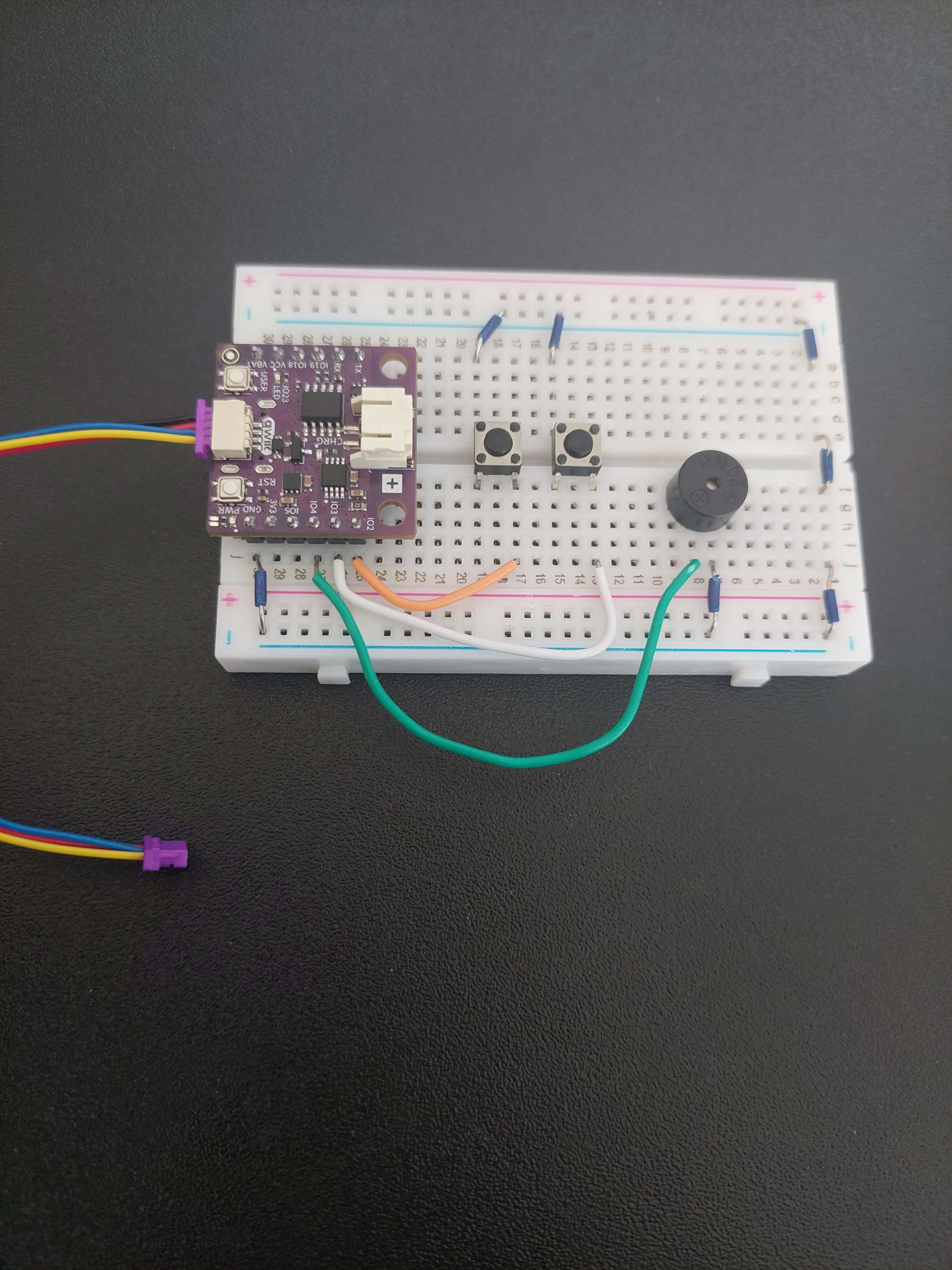
Follow the eleven steps below. Every photo is taken from the same position, so you can compare each one with the one before it and see exactly what changed.
1. Insert the NULA MINI board on the breadboard
Push the board into one end of the breadboard so that its two rows of pins sit on either side of the centre channel, with the chip facing down. Press it in evenly until all the pins are seated.
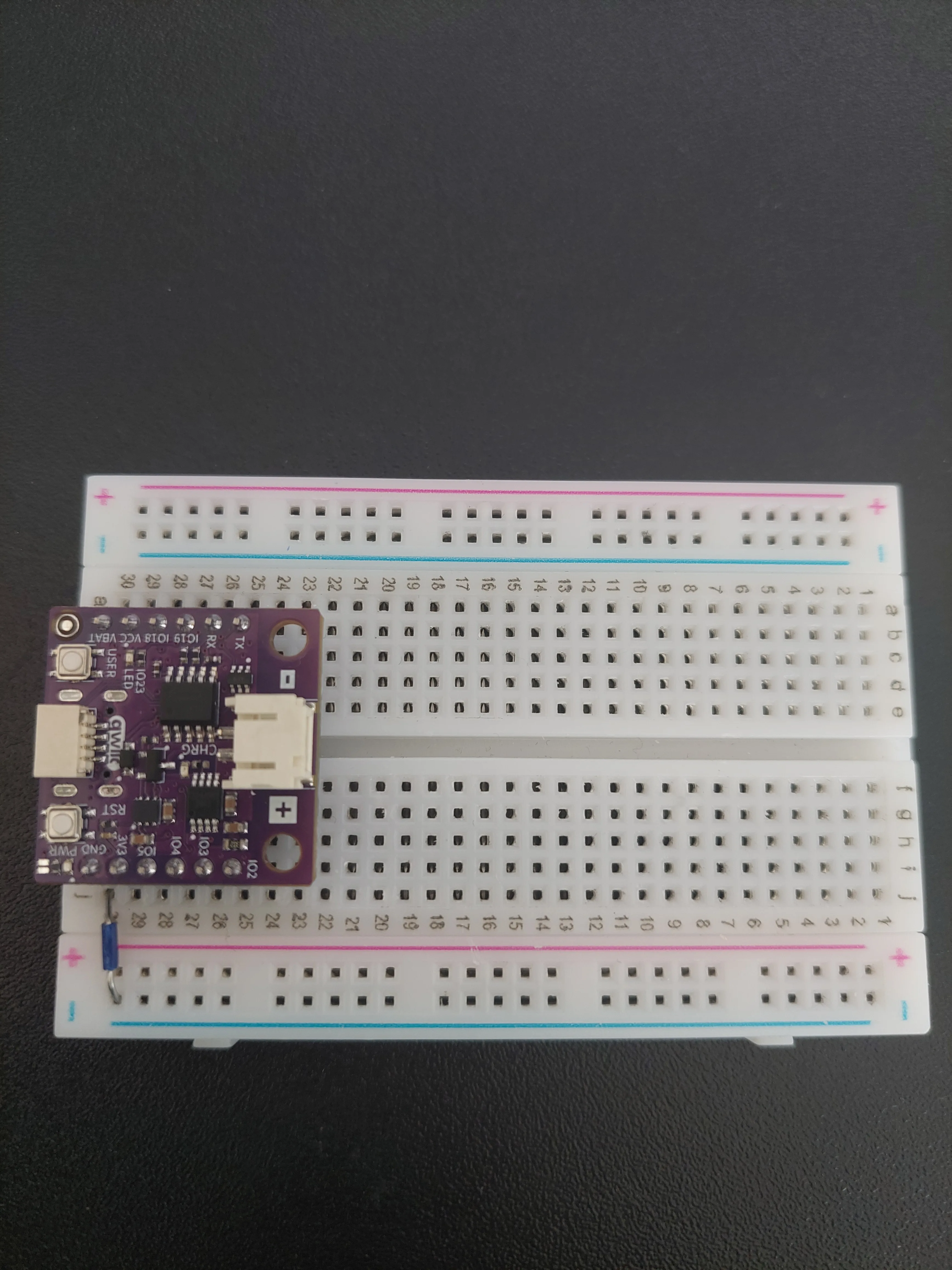
In the photos that follow, the board occupies rows 25 to 30.
2. Build one shared ground
Ground is the busiest connection in this project: both buttons and the buzzer need it. So the first job is to turn the two blue − rails into a single ground line that either side of the board can reach.
That takes four short jumpers:
| From | To | What it does |
|---|---|---|
j30 (GND) | f–j blue − rail | Brings ground off the board |
j1 | f–j blue − rail | Takes ground back onto row 1 |
e1 | f1 | Carries it across the centre channel |
a1 | a–e blue − rail | Feeds it into the other rail |
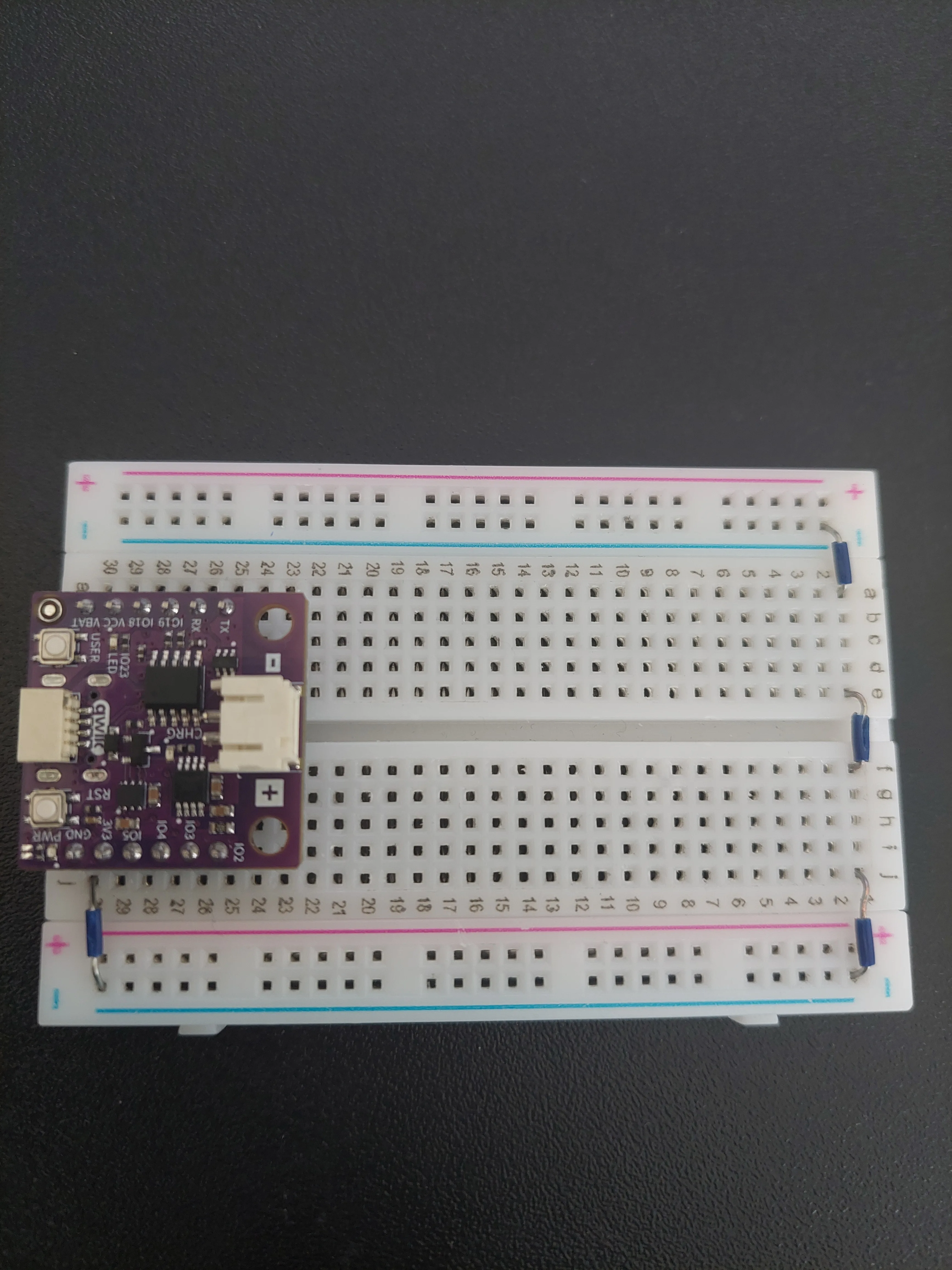
3. Place the two push buttons
Push the two buttons into the middle of the breadboard so that each one straddles the centre channel, a few rows clear of the board. Each button spans two rows.
In the photos they sit in rows 17 and 19 for the hour button, nearest the board, and rows 13 and 15 for the minute button.
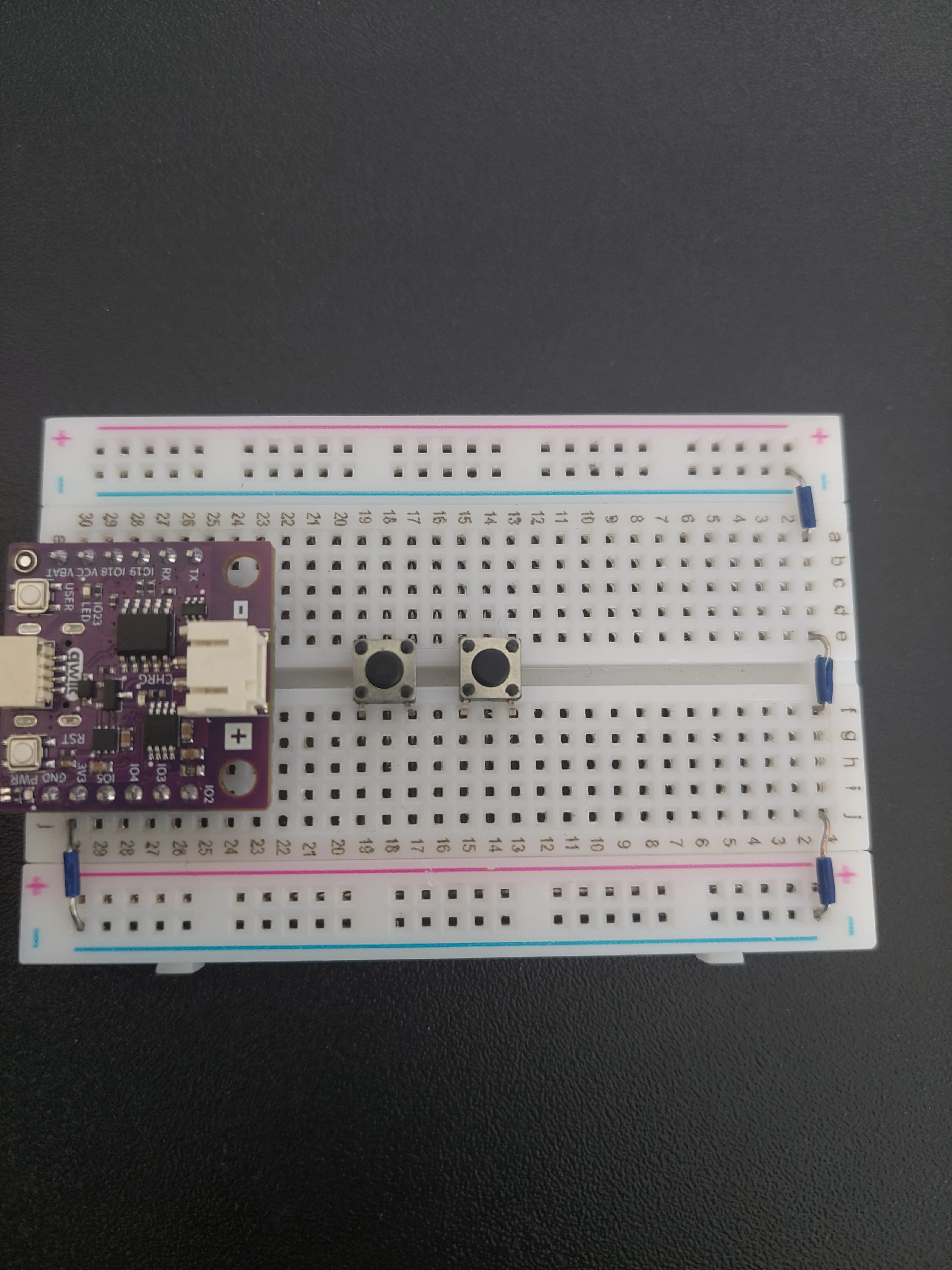
4. Ground both buttons
Two short jumpers, one per button, from the button's a–e side out to the blue − rail on that edge: a19 for the hour button and a15 for the minute button.
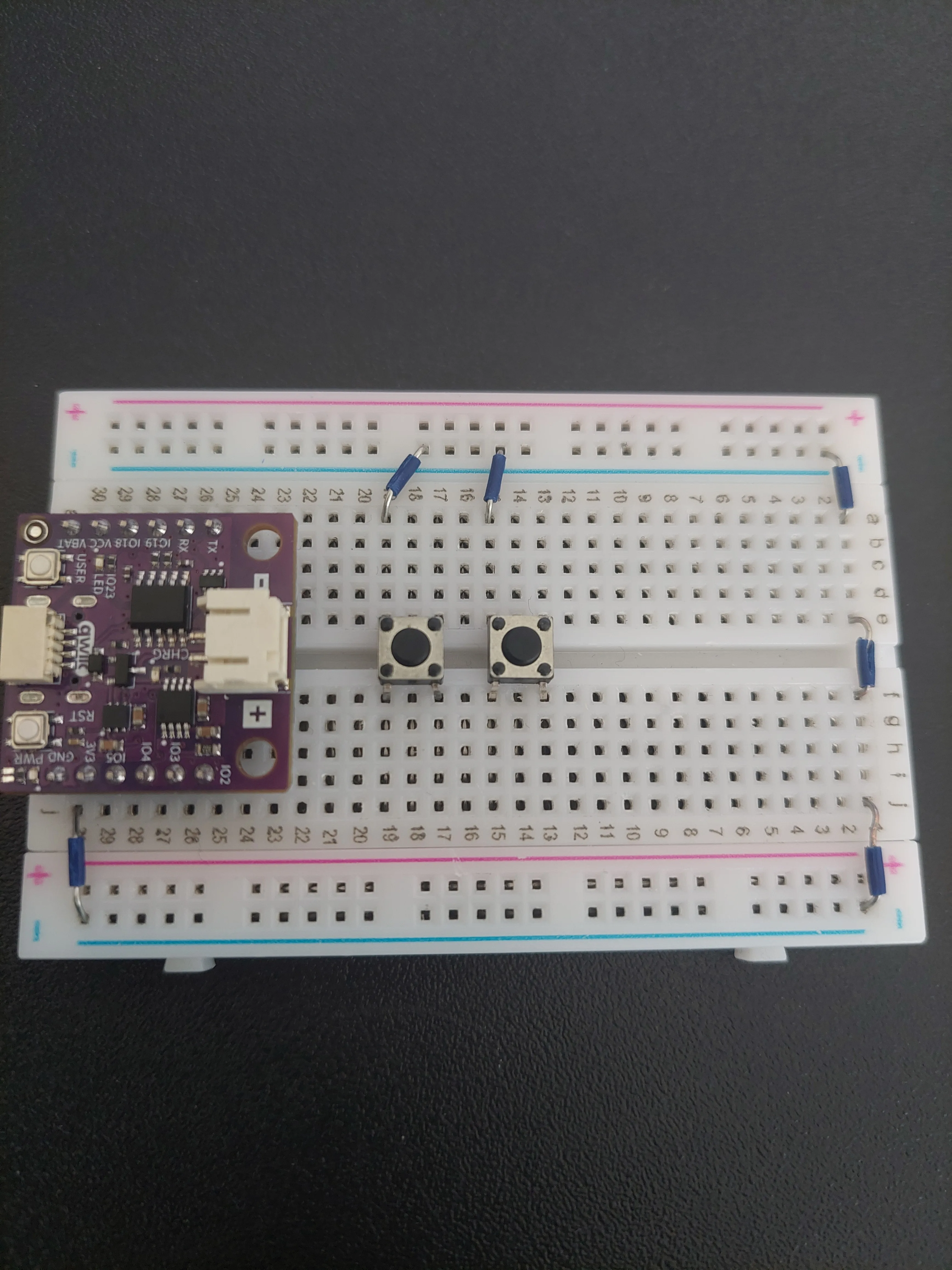
GND came off the board on the f–j side. Without those wires through row 1 this rail would be connected to nothing at all, and both buttons would be dead.5. Connect each button to its own pin
Now the two signal wires, both on the f–j side. Each runs from a board pin to the lower row of one button's pair:
| From | To | Button | Colour in the photo |
|---|---|---|---|
j25 (IO2) | j17 | Hour | Orange |
j26 (IO3) | j13 | Minute | White |
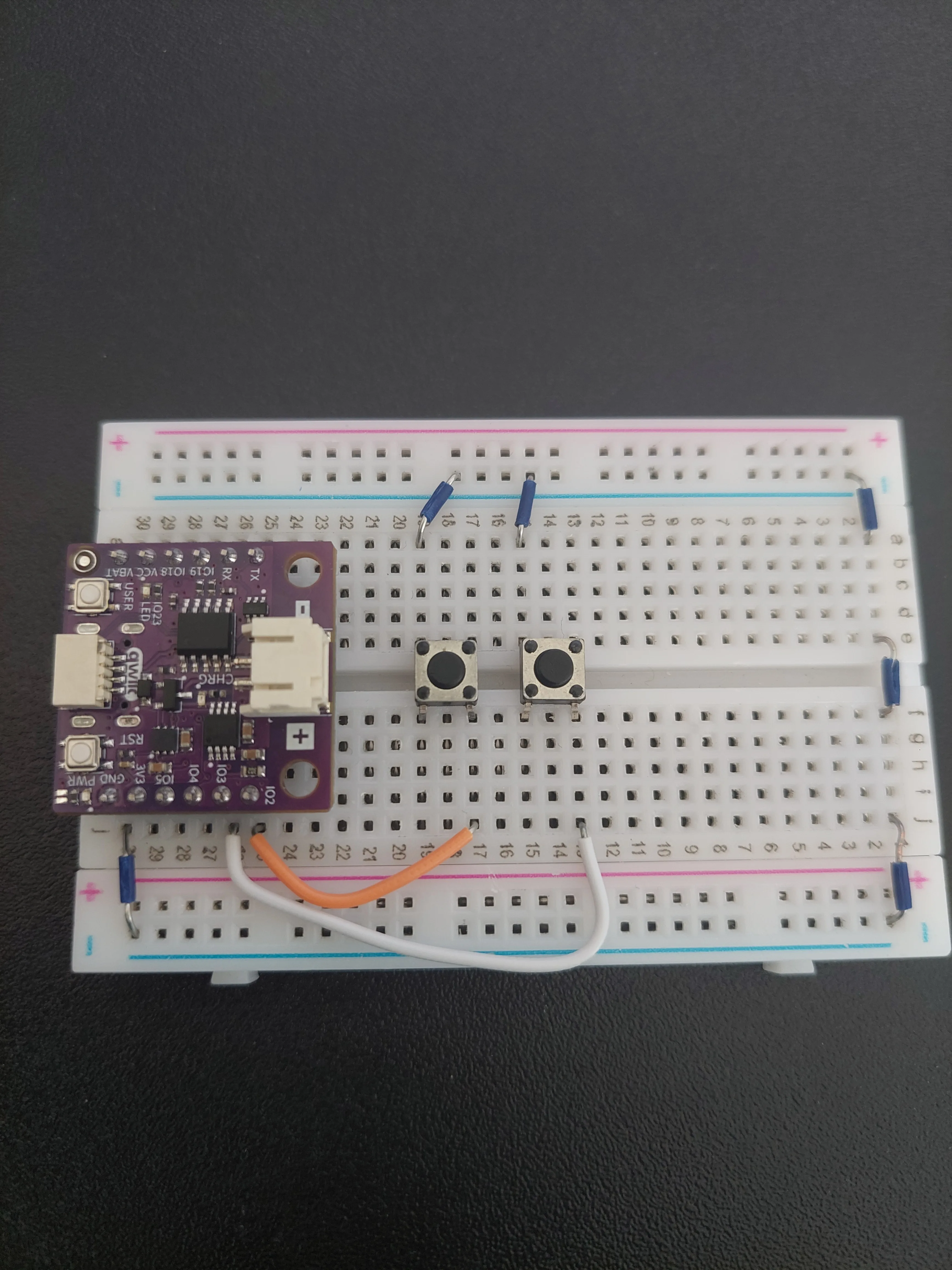
Notice that the two wires run in parallel and never cross. IO2, the pin nearest the buttons, goes to the nearest button. Swapping them swaps what the buttons do: the hour button would set minutes and the minute button hours.
6. Place the buzzer
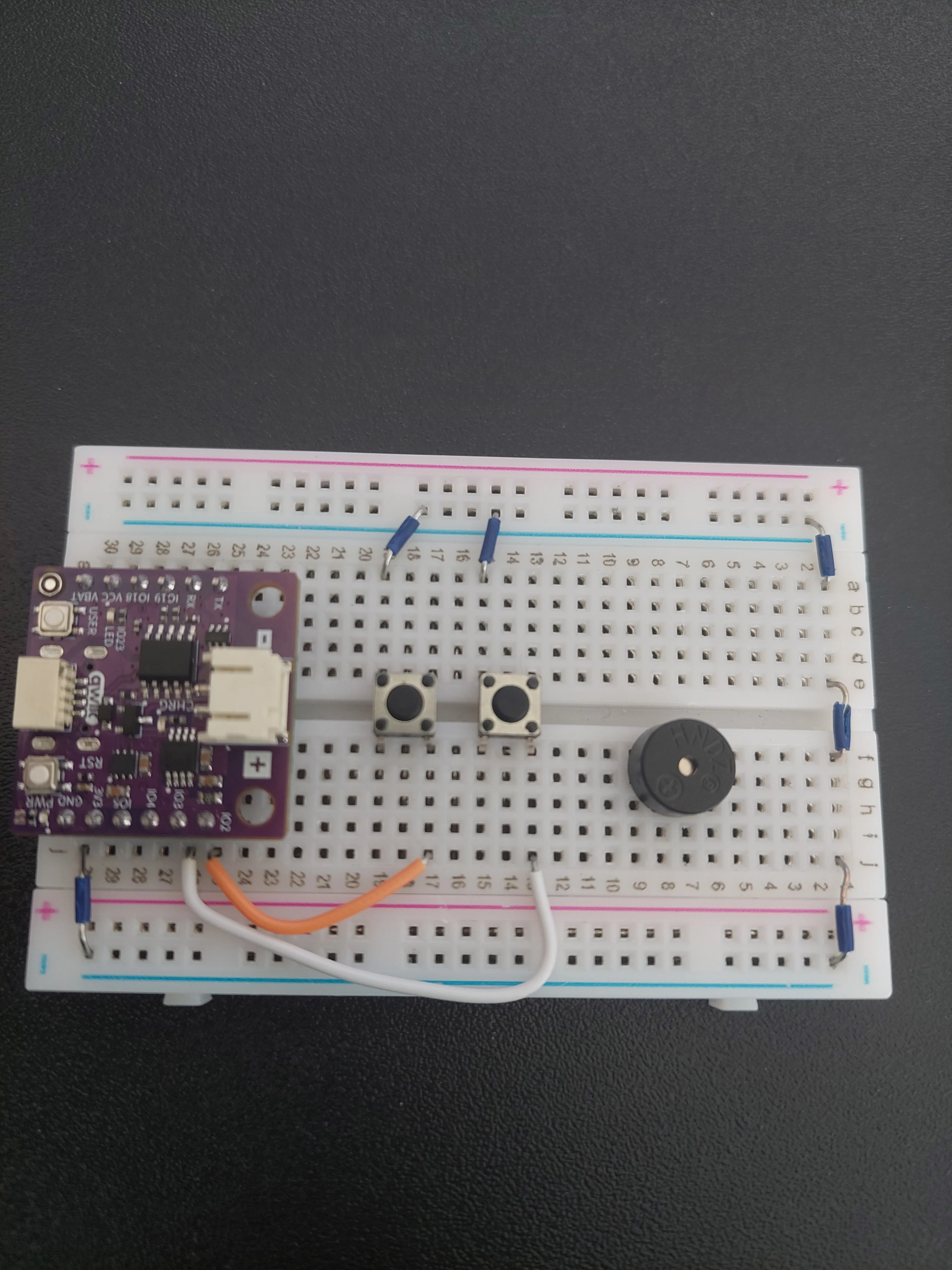
The buzzer goes on the f–j side at the far end of the breadboard, with its legs in two neighbouring rows, rows 7 and 8 in the photo.
Look at the top of its case before you push it in. Next to the moulded lettering there is a small + inside a circle, and the leg on that side of the case is the positive one. That leg goes into row 8, the row nearer the buttons.
7. Connect the buzzer to IO4
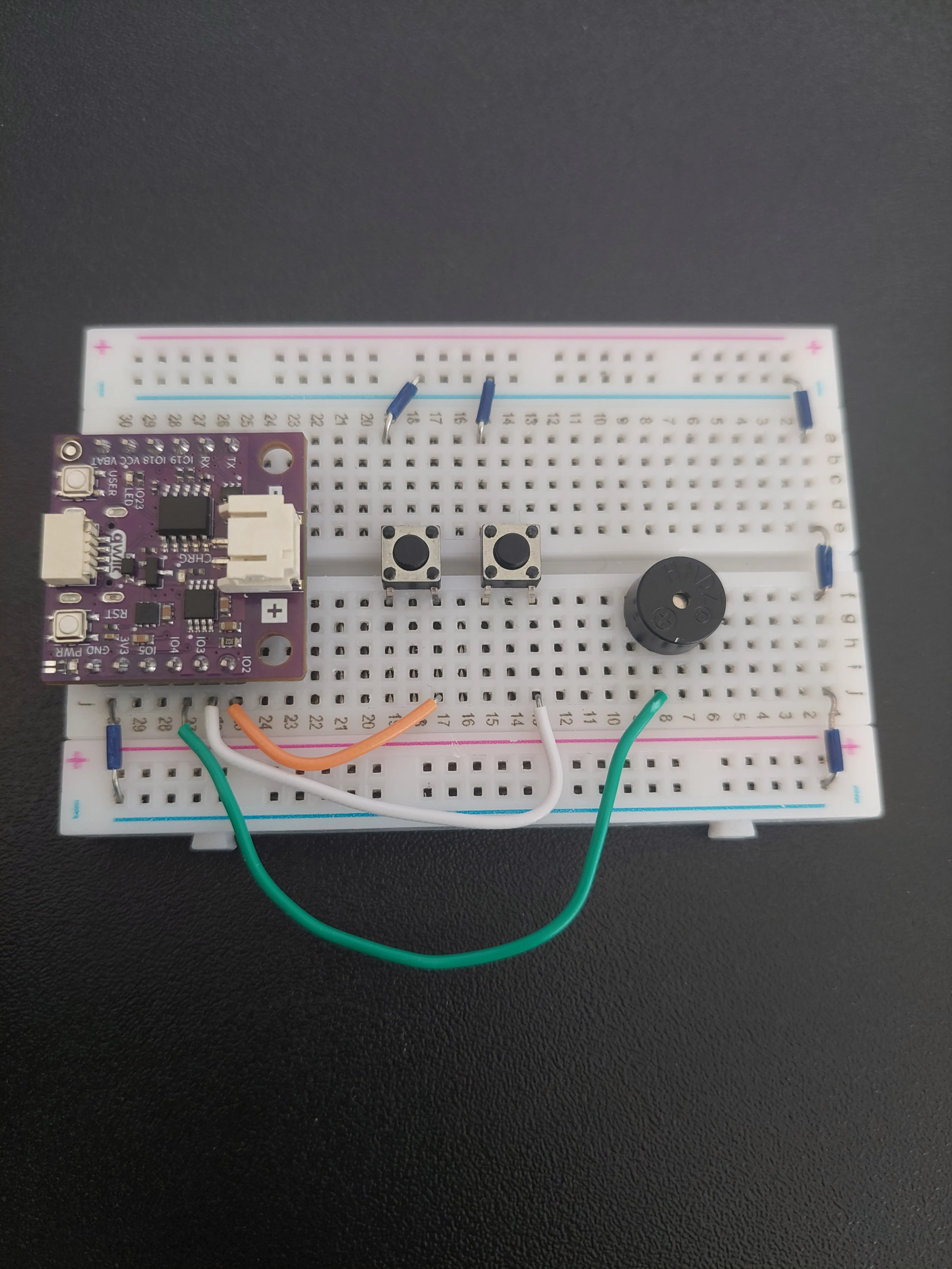
One jumper from j27, which is IO4, out to j8, the row holding the buzzer's + leg. This is the wire that carries the square wave.
8. Ground the buzzer
One more jumper, from j7 (the buzzer's other leg) down to the blue − rail on the same edge.
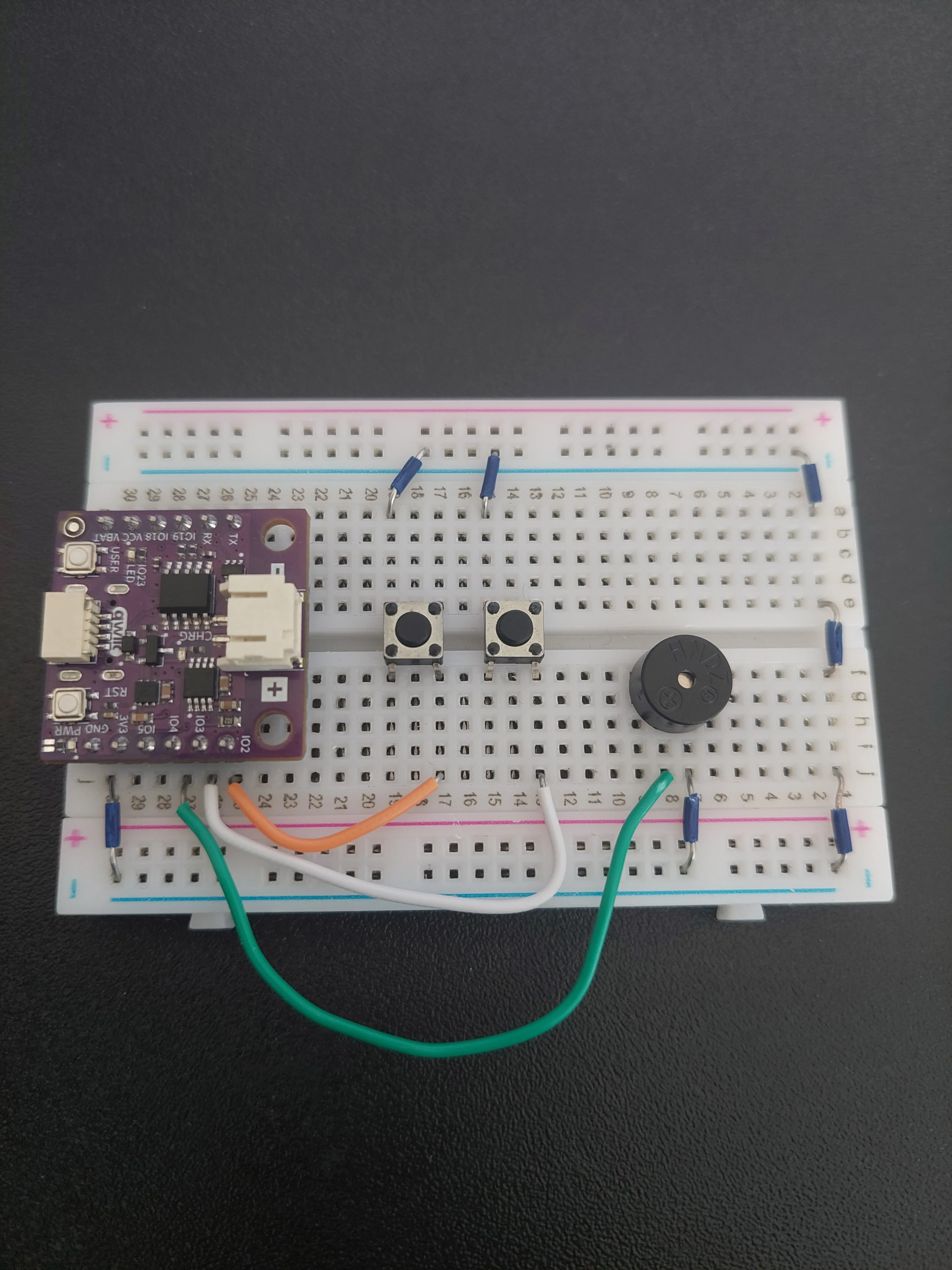
The loop is now closed: IO4 → buzzer → GND. The 12 mm case hides the legs once the buzzer is pushed in, so if you ever need to check this wiring again, read the two jumpers instead.
The breadboard is finished. Everything from here on simply plugs in.
9. Connect the Qwiic cable to the board
The LCD does not touch the breadboard at all. It connects over a single Qwiic cable, which carries power and both I2C signals in one plug.
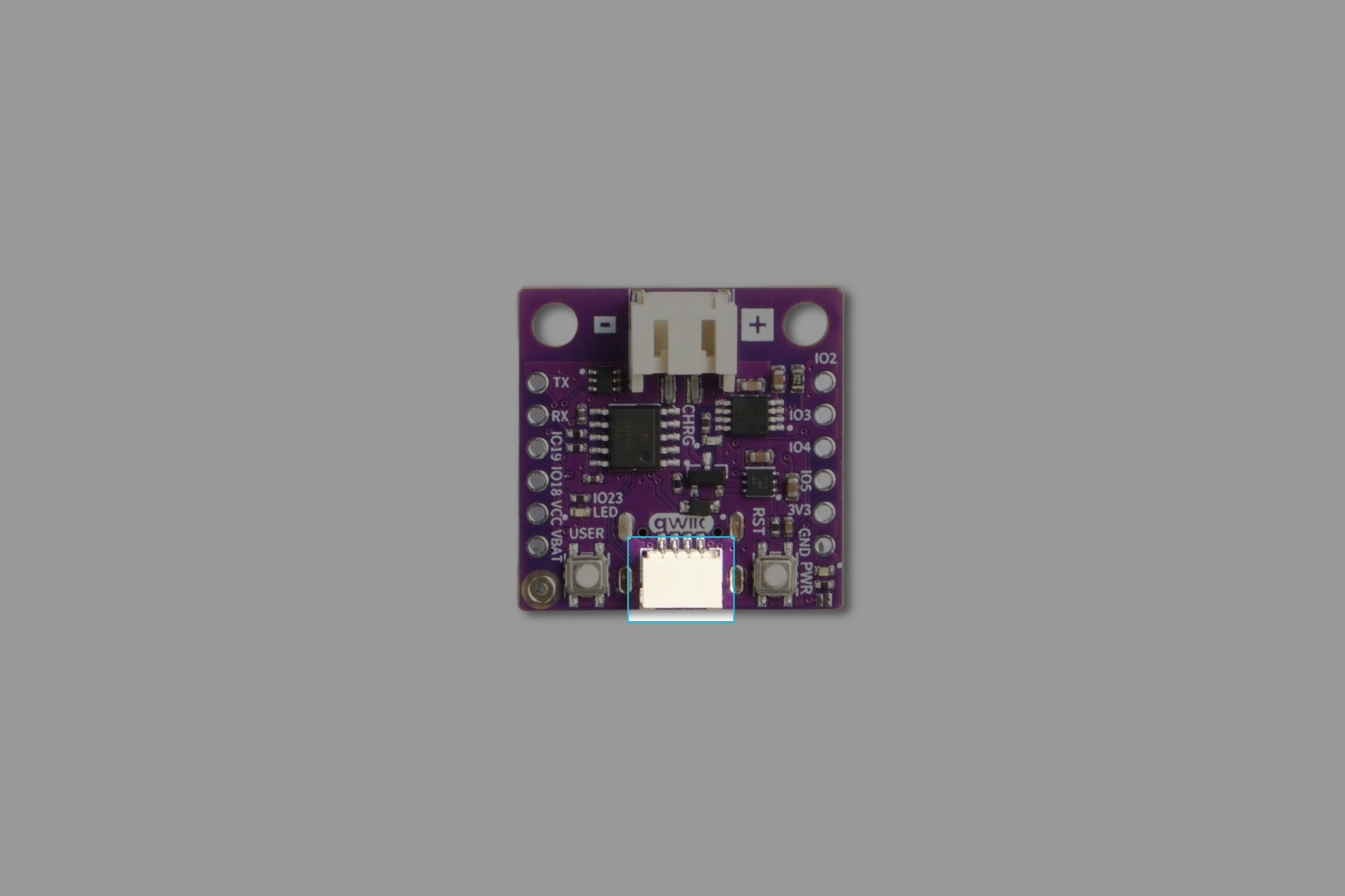
Find the white Qwiic socket on the NULA MINI and push one end of the cable into it. It only fits one way round.
10. Connect the other end to the LCD
Turn the display over. The purple board on its back is the I2C LCD ADAPTER, and it carries two Qwiic sockets, one at each end. Either one works: they are the same junction with two plugs.
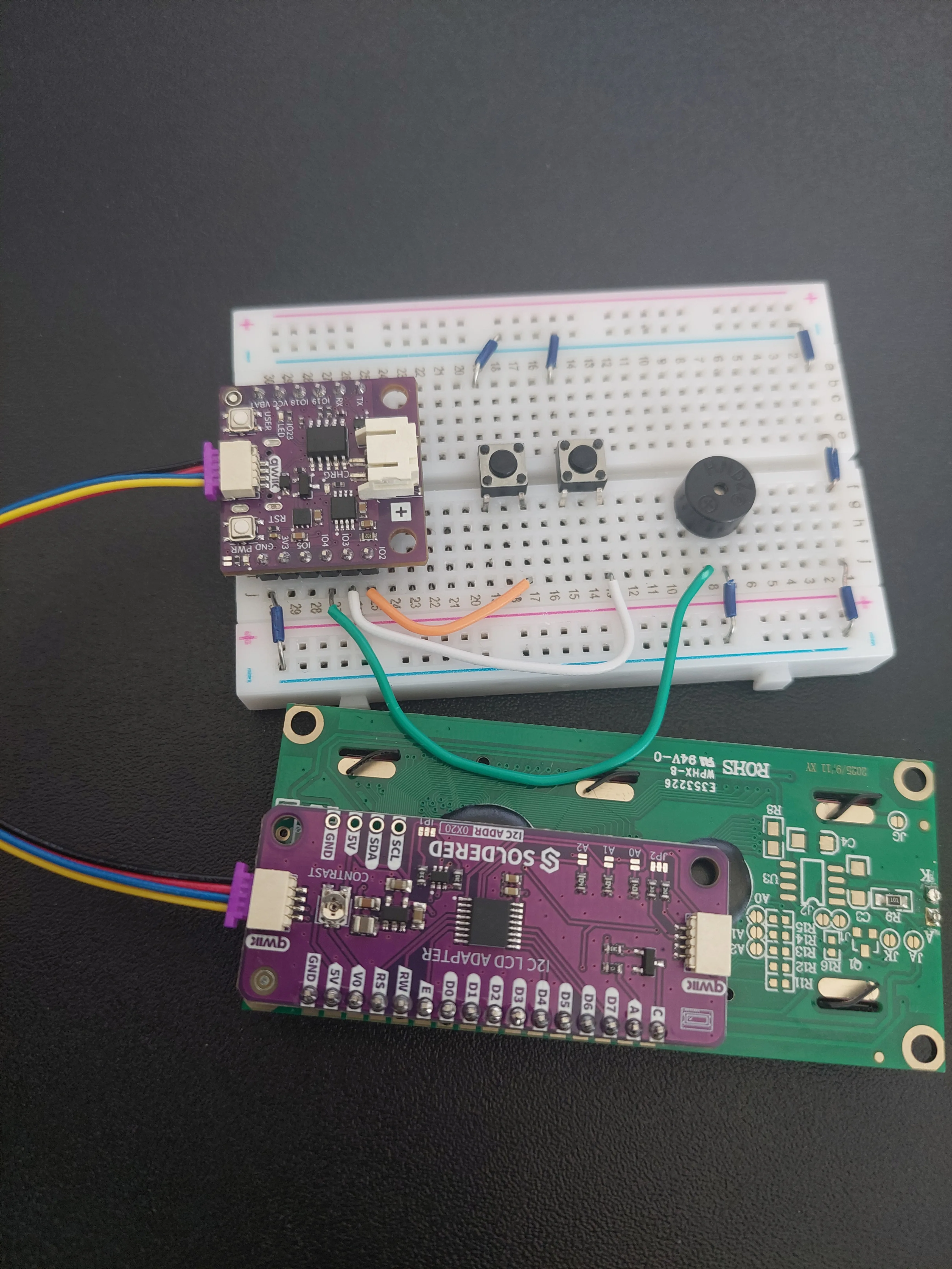
I2C ADDR 0X20 printed on the adapter is the display's address on the bus. The sketch never mentions it because the library already knows it: LCD lcd(16, 2) fills in 0x20 for you. The A0, A1 and A2 pads beside it can shift that address, which is what you would use if you ever wanted two displays on one board.11. Connect the board to your computer
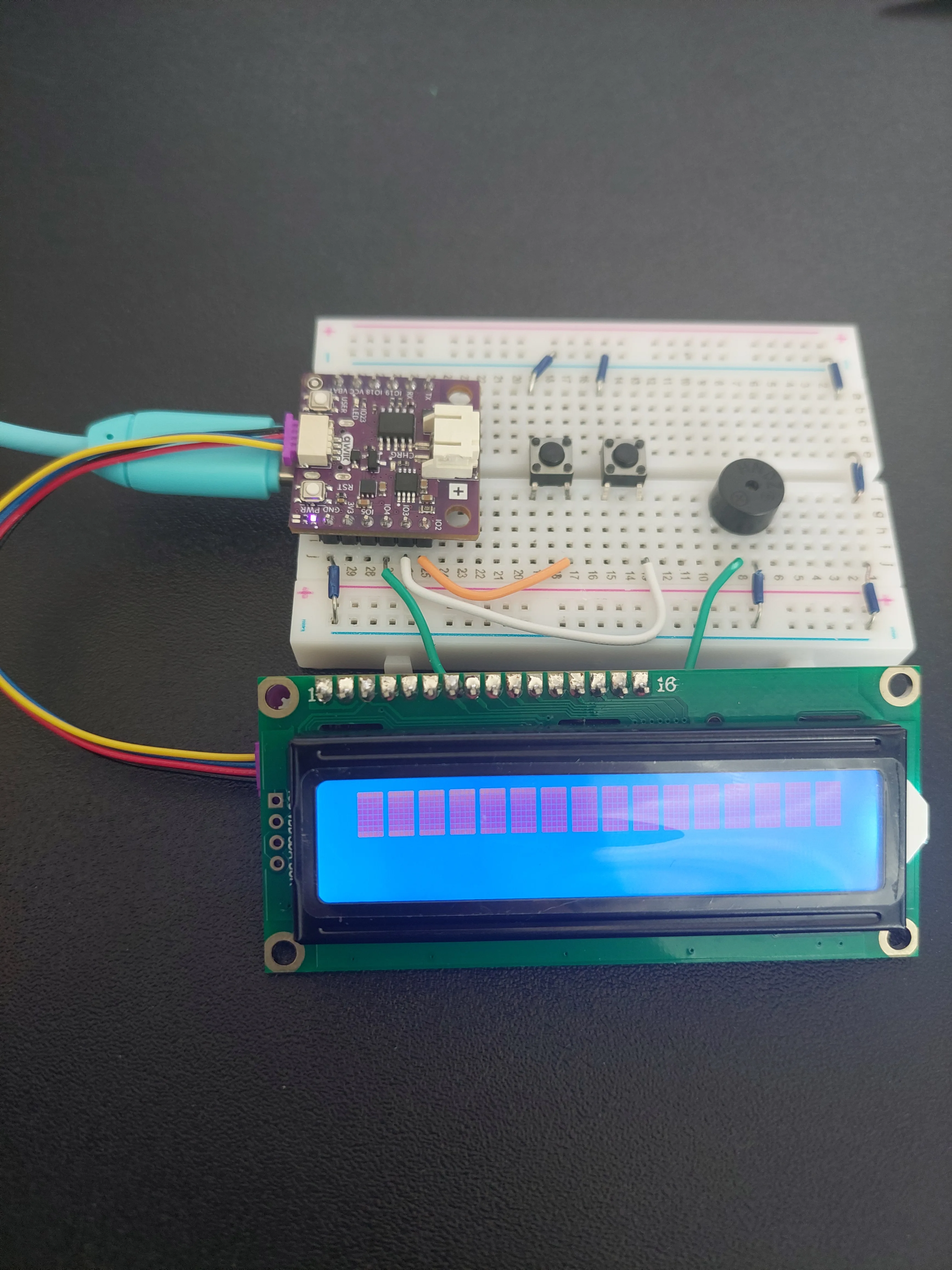
Plug the USB-C cable into the board. The PWR LED lights up, and the display's backlight comes on with it.
How the board knows the time
The NULA MINI has no clock of its own. Unplug it and it forgets what time it is. There is no battery keeping a clock ticking the way there is in a wristwatch or a PC.
So it asks. Once it is on the network it sends a short request to a time server and gets the current time back. The protocol for that is NTP, Network Time Protocol, and it is how nearly every connected device on earth keeps its clock right.
The sketch uses pool.ntp.org, a free worldwide service that passes your request to whichever server is nearest you. configTime() sets it going, and from that moment the board keeps its own count of the seconds, checking in again every minute so that it never drifts far.
Time zones are your job
An NTP server always answers in UTC, the world reference time. It has no idea where you are, so it cannot know what time it is for you. Turning UTC into local time is left to two numbers at the top of the sketch:
const long gmtOffset_sec = 0;
const int daylightOffset_sec = 0;
Both are in seconds, so one hour is 3600. The first is how far your time zone sits from UTC. The second is the extra hour for daylight saving, if your country uses it.
gmtOffset_sec = 3600 all year and daylightOffset_sec = 3600 from late March to late October. The sketch ships with both set to 0, which is why the display in the photos further down reads 10:29 when the clock on the wall said 12:29. If your clock is out by a whole number of hours, this is why. Nothing is broken.Why the alarm needs a memory
The board runs through loop() about ten times a second, and the alarm fires when the clock matches the alarm time. But a minute lasts sixty seconds, so a plain comparison would match roughly six hundred times in a row and the buzzer would never stop.
Two variables prevent that. alarmTriggered is set the moment the alarm goes off and blocks any further firing until you press a button. lastAlarmMinute remembers which minute it fired in, so that pressing a button to clear the display cannot immediately set it off again while that same minute is still running.
Code
Here is the full sketch. Set the board to Soldered NULA Mini ESP32C6 before uploading, and put your own network name and password into WIFI_SSID and WIFI_PASS.
/**
 **************************************************
 *
 * @file        7.7_Alarm_Clock.ino
 * @brief       Project that builds a Wi-Fi connected alarm clock. The board joins your network, asks an NTP server on
 *              the internet what the time is, and shows the current time on the LCD display. Two buttons set the alarm
 *              hour and minute, and when the alarm time is reached the buzzer sounds a series of beeps.
 *              It brings together the LCD from section 4, the button debouncing from section 2.2, the buzzer from
 *              section 2.4 and the Wi-Fi connection from section 6.
 *              For details, connection diagram and more, check out the example documentation at: <link placeholder>
 * @author      Soldered
 ***************************************************
 */

/*
The Soldered library for the LCD display.
*/
#include "LCD-SOLDERED.h"

/*
The WiFi library contains everything needed to join a Wi-Fi network.
*/
#include <WiFi.h>

/*
The time library gives us the functions for working with dates and times, and for asking an NTP server what the time is.
NTP stands for Network Time Protocol, and it is how nearly every device on the internet keeps its clock correct.
*/
#include <time.h>

/*
These two variables hold the name of your Wi-Fi network (the SSID) and its password. Replace the text between the
quotation marks with your own network details.
*/
const char* WIFI_SSID = "your ssid";
const char* WIFI_PASS = "your password";

/*
This is the address of the NTP server we ask for the time. pool.ntp.org is a free, worldwide service that hands your
request to whichever time server is nearest to you, so it is a good default to leave as it is.
*/
const char* ntpServer = "pool.ntp.org";

/*
NTP servers always answer in UTC, the world reference time, so we have to tell the board how far our own time zone sits
from it. The offset is given in seconds, so one hour is 3600. Croatia in winter is one hour ahead of UTC, which would
be 3600 here.
The second value is the extra offset for daylight saving time. Set it to 3600 during summer time in a country that uses
it, and leave it at 0 otherwise.
*/
const long gmtOffset_sec = 0;
const int daylightOffset_sec = 0;

/*
Here we create our display object, which we named "lcd". An object is our way of talking to the display: every function
we call on it, we call through this name. It needs no pin numbers because it uses easyC, which is Soldered's name for an
I2C connection over a single cable, and I2C always uses the same two pins on the board (IO6 and IO7 on the NULA board).
*/
LCD lcd(16, 2); // Qwiic 16x2 LCD

/*
These are the variables to which we pass the numbers of pins that we had connected the two BUTTONS and the buzzer to.
One button counts the alarm hour up, the other counts the alarm minute up.
The NULA board has a pin naming logic as follows: IO2, where 2 is the number that we give to the variable.
*/
const int BUTTON_HOUR = 2;
const int BUTTON_MIN  = 3;
const int BUZZER_PIN  = 4;

/*
These variables hold the alarm time we are counting towards, starting at 07:00, and remember whether the alarm has
already gone off, so that it sounds once and not over and over during the same minute.
*/
int alarmHour = 7;
int alarmMinute = 0;
bool alarmTriggered = false;

/*
This variable remembers which minute the alarm last went off in. Without it, stopping the alarm with a button press
inside the very minute it fired would let it fire again immediately, over and over until the minute was out. We start it
at -1, a value no real minute can have, so that the first alarm is never blocked.
*/
int lastAlarmMinute = -1;

/*
These are the variables used for button debouncing, the same technique explained in example 2.2. Because we have two
buttons here, each one needs its own pair of variables: one remembering its previous state and one remembering when
that state last changed.
*/
bool lastHourState = HIGH;
bool lastMinState = HIGH;
unsigned long lastHourChangeMs = 0;
unsigned long lastMinChangeMs = 0;
const unsigned long debounceMs = 25;

/*
These two variables control how often we ask the NTP server for the time again. A board's own clock drifts slowly, so
checking in every once in a while keeps it accurate.
*/
unsigned long lastSync = 0;
const unsigned long syncInterval = 60000;

/*
This is a function we wrote ourselves. It asks for the current time and reports whether it succeeded.
getLocalTime() fills in the structure we hand it and returns true on success or false on failure. On a failure the
structure is left exactly as it was, which would be full of meaningless values, so we pass that answer back to the
caller and let it decide what to do rather than using numbers we cannot trust.
The "*" in the parameter means we are handing over the location of the structure rather than a copy of it, which is what
allows the function to fill in our own variable instead of one of its own.
*/
bool getLocalTimeData(struct tm *timeinfo) {
  if (!getLocalTime(timeinfo)) {
    Serial.println("Failed to obtain time from NTP");
    return false;
  }
  return true;
}

/*
This function sounds the alarm. tone() makes the buzzer produce a sound of the given frequency, 1000 Hz in this case,
and noTone() stops it again. Repeating that five times in a row is what turns one long sound into a series of beeps.
Feel free to experiment with the frequency, the number of repeats and the two delays.
*/
void beepAlarm() {
  for (int i = 0; i < 5; i++) {
    tone(BUZZER_PIN, 1000);
    delay(300);
    noTone(BUZZER_PIN);
    delay(100);
  }
}

void setup() {

  /*
  Serial.begin() establishes serial communication between your board and your computer via a USB cable. We use it here
  to follow the connection to the network and to the time server.
  */
  Serial.begin(115200);

  /*
  Here we prepare the display. begin() starts the communication with it and backlight() turns on its light so the text
  is readable.
  */
  lcd.begin();
  lcd.backlight();

  /*
  pinMode() is a function that configures the specified pin to behave either as an input or as an output.
  The buzzer is something we write to, so it goes into OUTPUT mode, while the two buttons are things we read, so they
  go into INPUT_PULLUP mode. INPUT_PULLUP switches on a small resistor inside the chip that ties each pin to 3.3V,
  which means a pin sits at HIGH while its button is released and goes LOW while it is pressed.
  */
  pinMode(BUZZER_PIN, OUTPUT);
  pinMode(BUTTON_HOUR, INPUT_PULLUP);
  pinMode(BUTTON_MIN, INPUT_PULLUP);

  /*
  clear() wipes anything left on the screen from before, and setCursor() chooses where the next text will appear: the
  first number is the column and the second is the row, both counting from zero.
  */
  lcd.clear();
  lcd.setCursor(0, 0);
  lcd.print("Connecting WiFi");

  /*
  WiFi.begin() starts the connection attempt. The function only starts the process, it does not wait for it to finish,
  so we wait for it ourselves in the loop below. WiFi.status() tells us the current state and WL_CONNECTED is the value
  it reports once we are online.
  */
  WiFi.begin(WIFI_SSID, WIFI_PASS);
  while (WiFi.status() != WL_CONNECTED) {
    delay(500);
    Serial.print(".");
  }

  Serial.println("\nWiFi connected!");
  lcd.clear();
  lcd.print("WiFi connected");
  delay(1000);

  /*
  configTime() tells the board which NTP server to use and how far our time zone is from UTC, and starts the first
  request for the time in the background. It returns straight away, before any answer has arrived.
  */
  configTime(gmtOffset_sec, daylightOffset_sec, ntpServer);

  /*
  So here we wait for that first answer, because until it arrives the board has no idea what time it is and would show
  nonsense on the display. We give it up to ten seconds and then carry on either way, so that a missing internet
  connection cannot leave the clock stuck here forever.
  */
  lcd.clear();
  lcd.print("Syncing time...");
  struct tm startupTime;
  unsigned long syncStart = millis();
  bool timeReady = false;
  while (!timeReady && millis() - syncStart < 10000) {
    timeReady = getLocalTime(&startupTime);
    delay(200);
  }

  lcd.clear();
  if (timeReady) {
    Serial.println("Time synced!");
    lcd.print("Time synced!");
    lastSync = millis();
  } else {
    Serial.println("Time sync failed, the clock will keep trying.");
    lcd.print("Sync failed!");
  }
  delay(1000);
  lcd.clear();
}

void loop() {

  /*
  Here we ask for the current time through our own function above. A struct tm holds a full date and time split into
  separate fields, of which we only use two: tm_hour and tm_min.
  */
  struct tm timeinfo;

  /*
  If we could not read the time, there is nothing sensible to show and certainly nothing to compare the alarm against,
  so we wait a moment and try again on the next pass. return ends this pass through loop() early, and because the board
  calls loop() again immediately we are straight back at the next attempt.
  */
  if (!getLocalTimeData(&timeinfo)) {
    delay(1000);
    return;
  }

  /*
  sprintf() builds a piece of text out of several values, following a pattern we give it. "%02d" means "a whole number
  written with at least two digits, padded with a zero if needed", which is what turns 7 minutes past into "07" instead
  of "7". The result is stored in the timeStr array and then printed to the display.
  */
  char timeStr[6];
  sprintf(timeStr, "%02d:%02d", timeinfo.tm_hour, timeinfo.tm_min);
  lcd.setCursor(0, 0);
  lcd.print("Time: ");
  lcd.print(timeStr);

  /*
  On the second line we show the alarm time. Here we pad the numbers by hand instead of using sprintf(): if the value is
  smaller than 10 we print a zero in front of it first.
  */
  lcd.setCursor(0, 1);
  lcd.print("Alarm ");
  if (alarmHour < 10) lcd.print("0");
  lcd.print(alarmHour);
  lcd.print(":");
  if (alarmMinute < 10) lcd.print("0");
  lcd.print(alarmMinute);

  /*
  This is the debouncing logic for the hour button, the same one explained in example 2.2. digitalRead() reads the value
  from the pin, millis() returns the number of milliseconds passed since the board began running the current program,
  and together they let us ignore any change that comes too soon after the previous one to be a real press.
  Because the buttons use pull-up resistors, the readings are the other way around from what you might expect: a press
  is the moment the reading goes from HIGH to LOW, and that is exactly the moment we count the hour up. After 23 we
  start over at 0, since there is no hour 24.
  */
  bool hourReading = digitalRead(BUTTON_HOUR);
  unsigned long now = millis();
  if (hourReading != lastHourState && (now - lastHourChangeMs) > debounceMs) {
    lastHourChangeMs = now;
    if (lastHourState == HIGH && hourReading == LOW) {
      alarmHour++;
      if (alarmHour > 23) alarmHour = 0;
    }
    lastHourState = hourReading;
  }

  /*
  The very same logic for the minute button, counting up to 59 before starting over.
  */
  bool minReading = digitalRead(BUTTON_MIN);
  if (minReading != lastMinState && (now - lastMinChangeMs) > debounceMs) {
    lastMinChangeMs = now;
    if (lastMinState == HIGH && minReading == LOW) {
      alarmMinute++;
      if (alarmMinute > 59) alarmMinute = 0;
    }
    lastMinState = minReading;
  }

  /*
  Here we check whether it is time for the alarm. All three conditions have to be true at once: the hour has to match,
  the minute has to match, and the alarm must not have gone off already. That last check is what the alarmTriggered
  variable is for, since without it the alarm would sound again and again for the whole minute.
  */
  if (timeinfo.tm_hour == alarmHour && timeinfo.tm_min == alarmMinute && !alarmTriggered
      && timeinfo.tm_min != lastAlarmMinute) {
    alarmTriggered = true;
    lastAlarmMinute = timeinfo.tm_min;
    lcd.clear();
    lcd.setCursor(0, 0);
    lcd.print("ALARM!");
    Serial.println("Alarm Triggered!");
    beepAlarm();
  }

  /*
  Pressing either button after the alarm has gone off clears the warning from the display and arms the alarm again for
  the next day.
  */
  if (alarmTriggered && (hourReading == LOW || minReading == LOW)) {
    alarmTriggered = false;
    lcd.clear();
  }

  /*
  And here we ask the NTP server for the time again every so often, so that the clock does not drift.
  */
  if (millis() - lastSync > syncInterval) {
    configTime(gmtOffset_sec, daylightOffset_sec, ntpServer);
    lastSync = millis();
  }

  /*
  A short pause so the display is not rewritten thousands of times per second. Keeping it short also keeps the buttons
  feeling responsive.
  */
  delay(100);
}
What you should see
Starting up
The sketch narrates its own start-up on the display, one screen at a time. First it announces that it is joining the network:
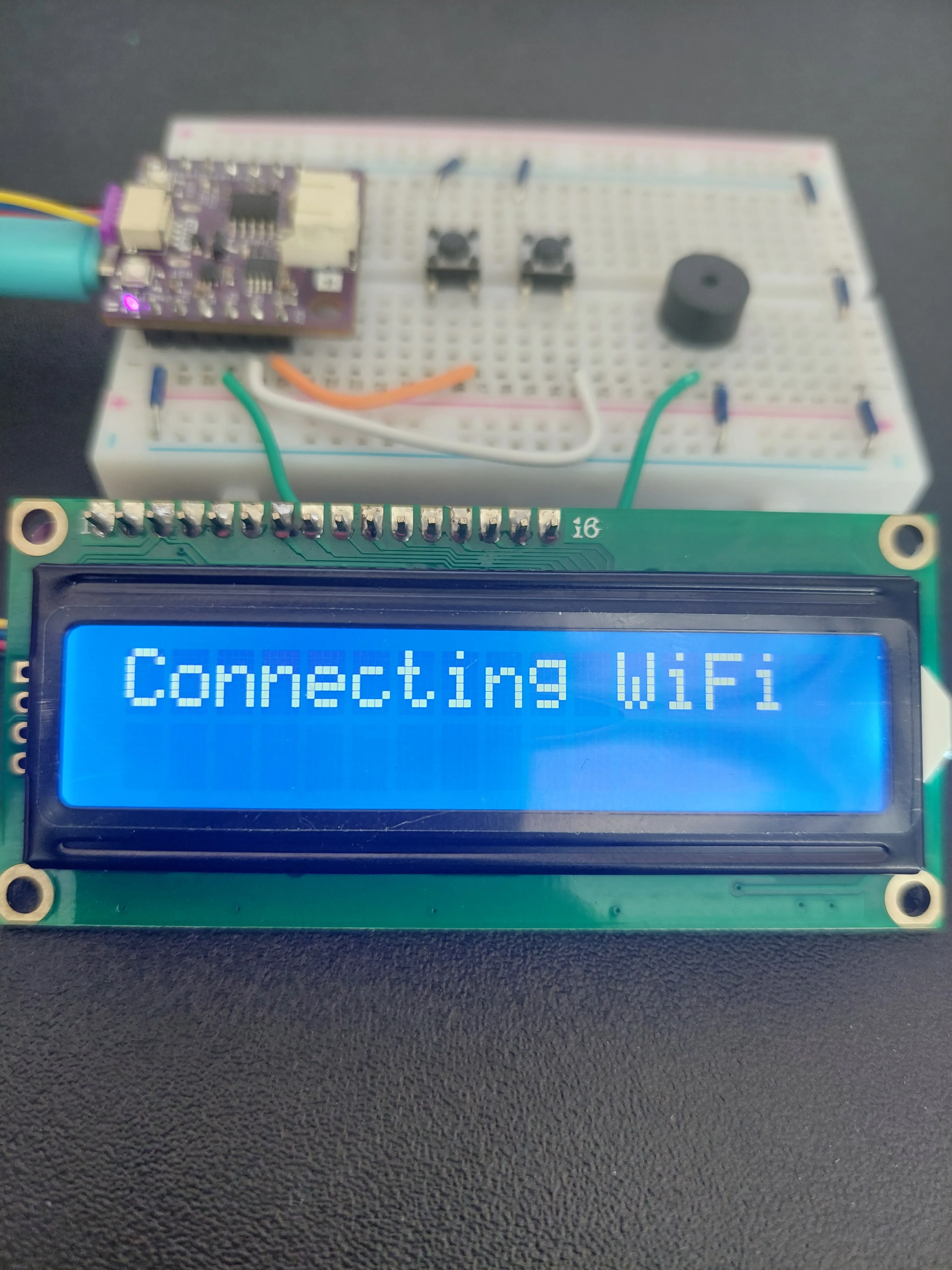
WIFI_SSID and WIFI_PASS for typos rather than the wiring.Once it is on, you get a second of confirmation:
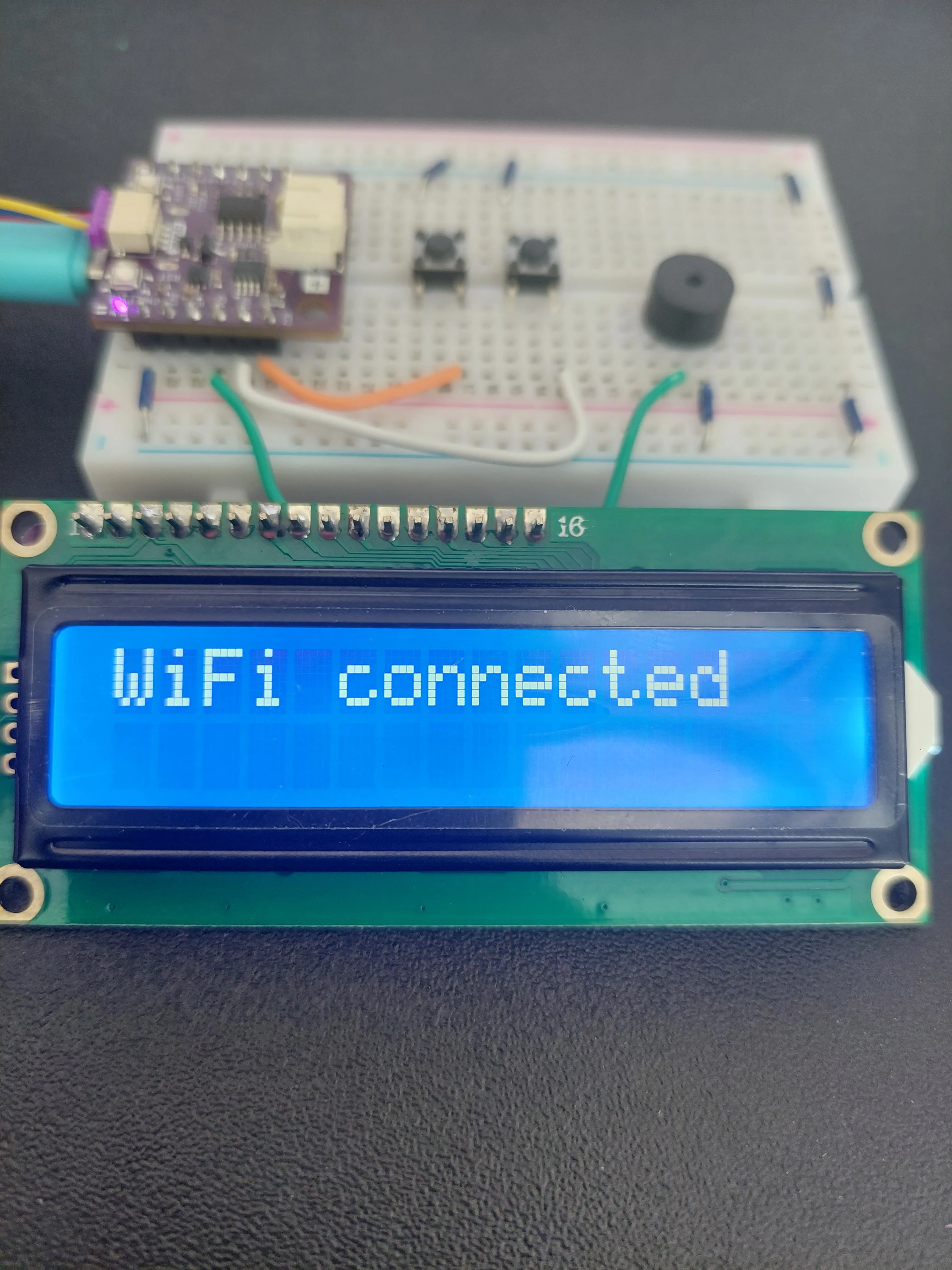
Then the board asks the time server for the time. configTime() returns immediately, before any answer has arrived, so the sketch waits here for up to ten seconds:
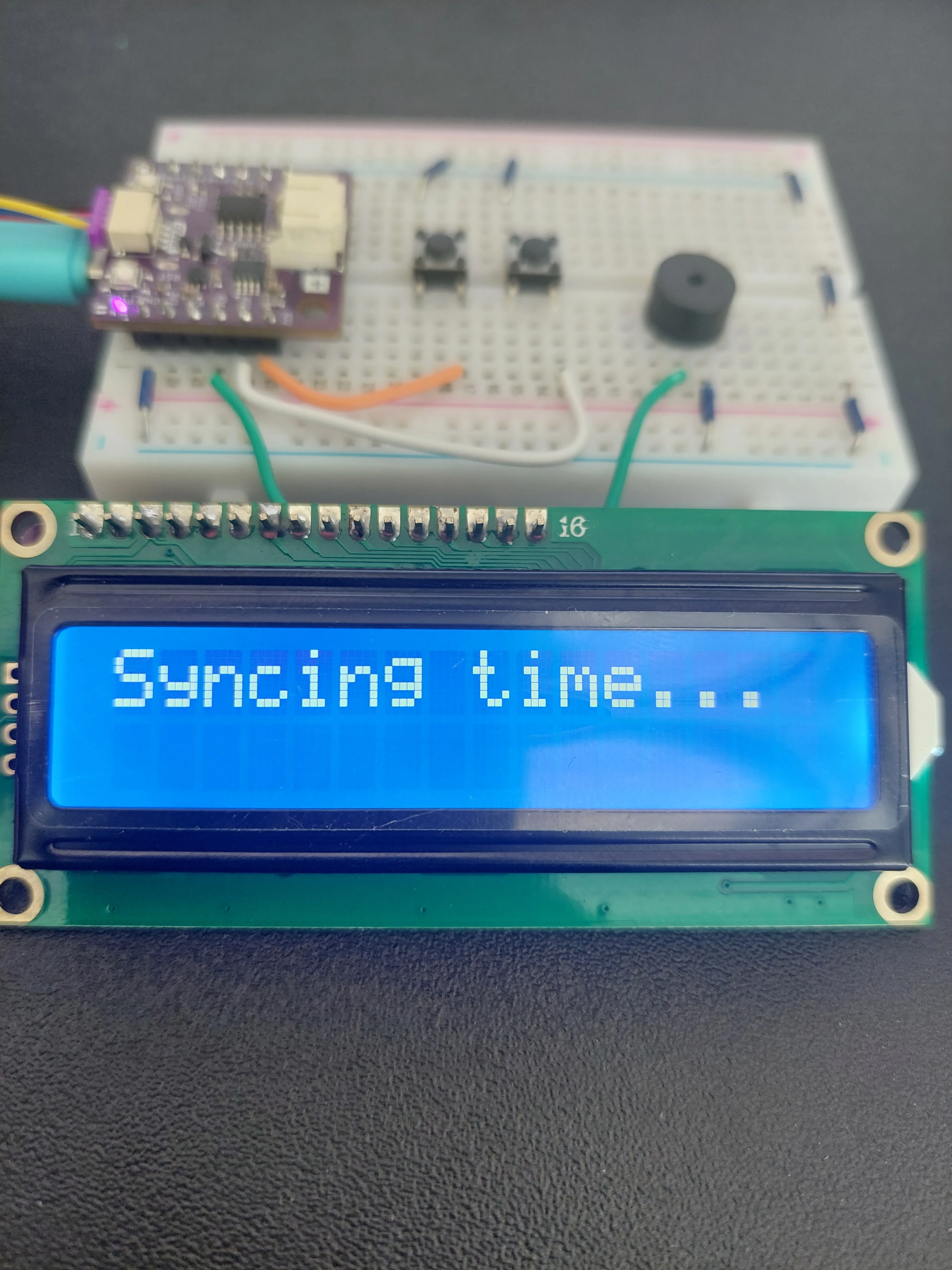
If the answer arrives you see Time synced! for a second and the clock starts. If it does not, you get Sync failed! instead, and the clock carries on anyway, retrying every minute, so a slow network delays the first reading but does not hang the project.
On the Serial Monitor
Open the Serial Monitor at 115200 baud and reset the board. The whole start-up fits in a few lines:

ESP-ROM:esp32c6-..., SPIWP, load: and entry are printed by the chip's built-in bootloader on every reset, before your program starts. They look alarming and mean nothing is wrong.4s are not from the sketch either. They come from inside the LCD library: lcd.begin() sends the display three setup messages and prints the result of each one. You never saw them in 4.1 or 4.2 because those sketches never call Serial.begin(), so there was nowhere for the numbers to go. This one does, so they show up. Ignore them. The display works, as the photos on this page show.Each dot is one turn of the waiting loop, and each turn takes 500 ms. Counting them tells you exactly how long the board took to join the network: twelve dots here, so six seconds. If you ever want to know whether your network is slow to hand out addresses, that row of dots is the measurement.
The clock running
After the start-up screens clear, the display settles into the two lines it will show from then on: the current time on top, the alarm time underneath:
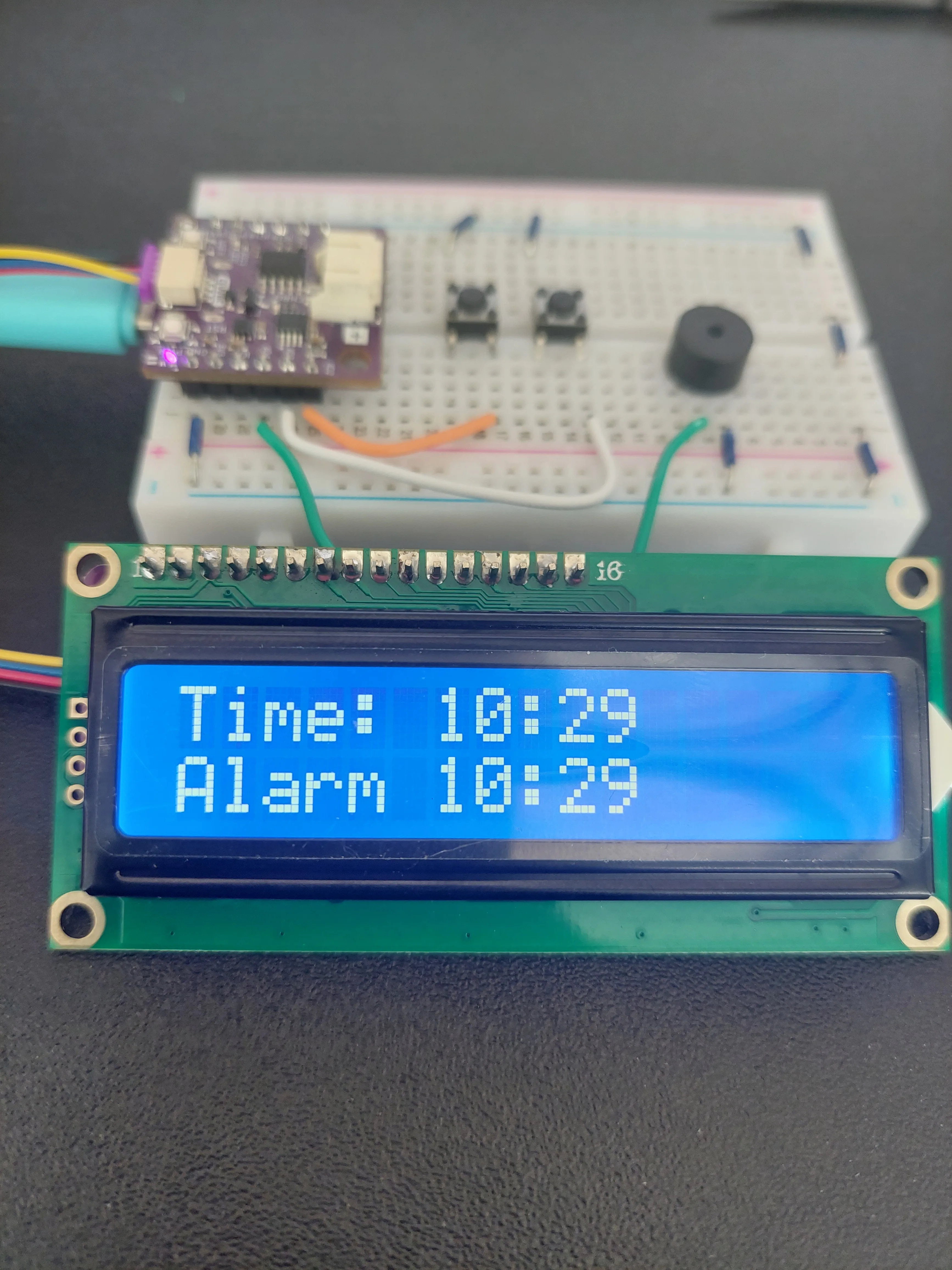
Both are padded to two digits, so seven minutes past shows as 07 and not 7. The top row does that with sprintf() and %02d; the bottom row does the same job by hand, printing a 0 first whenever the number is below ten. Two ways to reach the same result, side by side on one screen.
10:29 because the sketch ships with gmtOffset_sec = 0 and is therefore showing UTC. It was 12:29 in the room. Set the offset and the top row becomes your local time.Setting and hearing the alarm
The alarm starts at 07:00. Press the button on IO2 to count the hours up and the one on IO3 to count the minutes, and watch the bottom row change. Both wrap round: 23 goes back to 0, and 59 back to 0.
To hear the alarm without waiting all day, set it to the minute that is about to arrive. When the clock catches up, the top row is replaced:
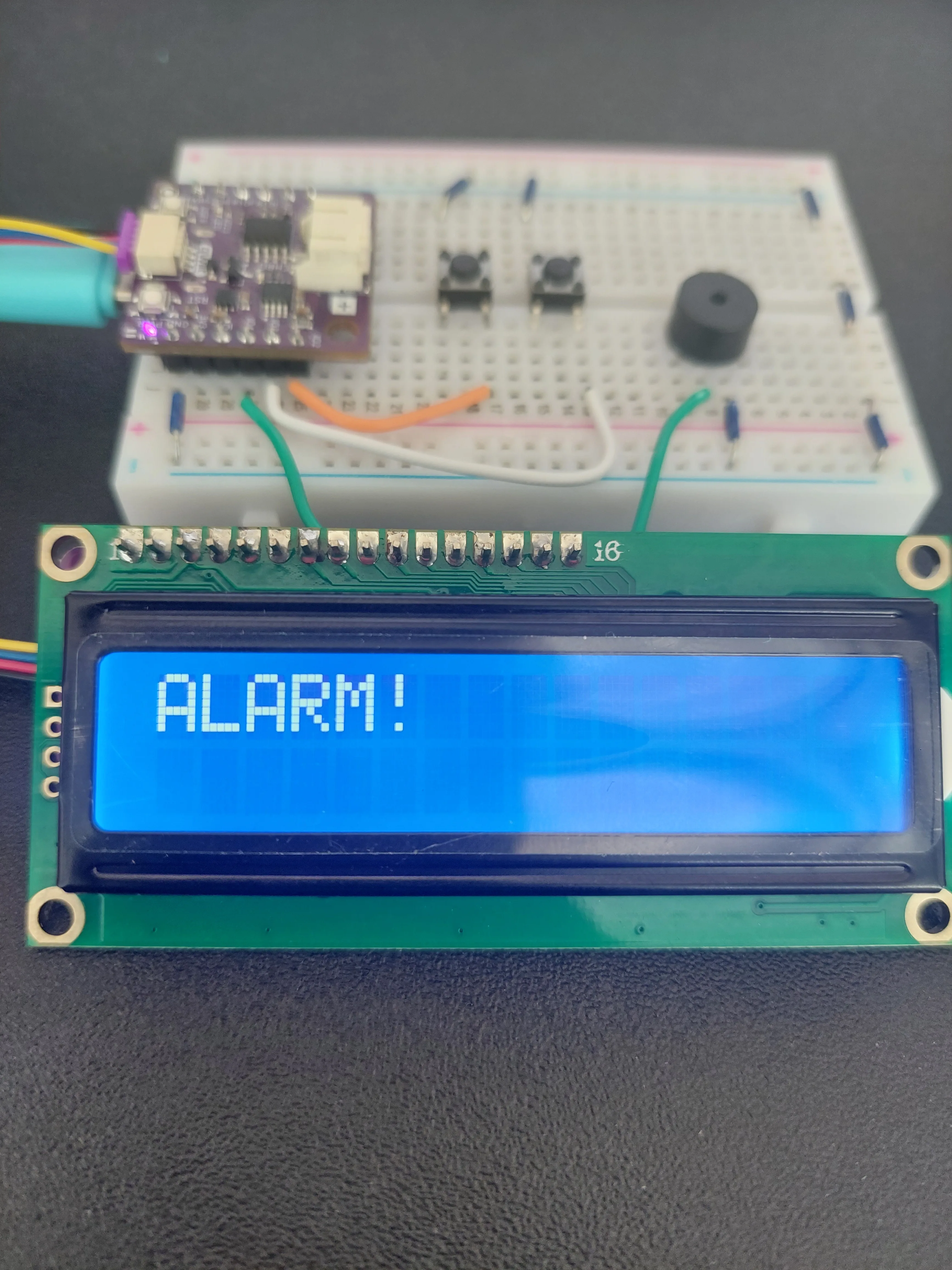
beepAlarm() plays five beeps of 300 ms with 100 ms of silence between them, and the display is not touched again until it finishes. The moment the beeping stops, loop() runs once more and writes the time back over the top of ALARM!. If you want to photograph it, you have one shot as the beeping starts.The Serial Monitor prints Alarm Triggered! at the same moment, which is useful if you missed the screen.
ALARM! from the display and arms the alarm again for next time.If something is not right
The display is lit but blank. This one has three different causes, and the Serial Monitor tells them apart in seconds, so open it before you touch the wiring.
- Nothing at all after the boot messages, or a row of solid blocks. The sketch is not reaching the display. Check the Qwiic cable is properly home at both ends, and that the board selected in the IDE is Soldered NULA Mini ESP32C6. A different ESP32 variant puts I2C on different pins, and the sketch will compile and upload perfectly while never once reaching the display.
- The Monitor shows the dots and
Time synced!, but the screen stays dark. The board is talking to the display and the display is simply too faint to read. Turn theCONTRASTtrimpot on the purple adapter board. - The Monitor repeats
Failed to obtain time from NTP. The board is on the network but cannot get the time, soloop()gives up before it ever writes anything. The screen is blank because there is nothing to show. Some guest and corporate networks block time servers.
The clock is wrong by a whole number of hours. That is the time zone offset, not a fault. See above.
One button does nothing. Check it is using one leg from each side of the centre channel. A button wired with both wires on the same side reads as permanently pressed, and one wired with the ground wire in the wrong row does nothing at all.
The buzzer is silent but ALARM! appears. The code is fine and the fault is in the last two wires. Check that the buzzer's legs really are in two different rows, and that IO4 is the pin at j27. On the other side of the board, a27 is IO19.
Full example
Check out the full example code on the link below:
7.7_Alarm_Clock.ino
Wi-Fi connected alarm clock: the board gets the time from an NTP server, shows it on a Qwiic LCD, and sounds a buzzer at an alarm time set with two buttons.