7.8 LED Traffic Light
Three LEDs, three resistors, and a program that walks through a fixed sequence of steps without ever stopping to wait. This project builds a miniature European traffic light (green, blinking green, orange, red, then red and orange together) and introduces the finite state machine, the pattern almost every real embedded program is built on.
In this documentation you will learn:
- What a finite state machine is, and how three variables are enough to build one
- How to run a timed sequence with
millis()instead ofdelay() - How to make one LED blink inside a state while that state's own timer keeps running
- How to follow a program's progress in the Serial Monitor
Hardware required
- 1x Soldered NULA MINI board
- 1x Breadboard
- 1x Green LED
- 1x Orange or yellow LED
- 1x Red LED
- 3x 330 Ω resistors
- 7x Jumper wires
- 1x USB-C cable
Putting the components together
Everything in this build sits on the f–j side of the breadboard. Nothing crosses the centre channel, and the same four-part chain is repeated three times, six rows further along each time.
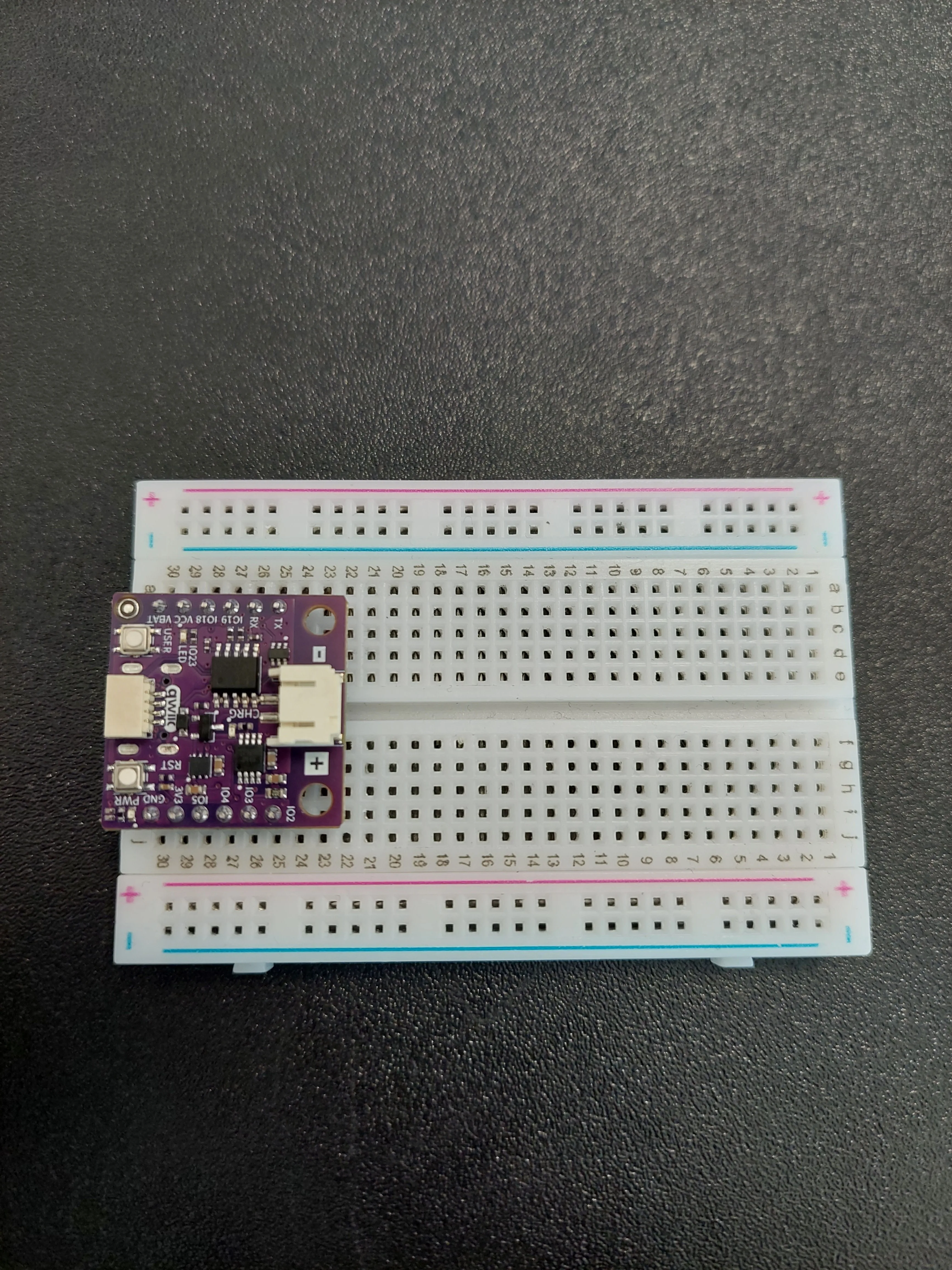
1. Insert the board
Push the NULA MINI into one end of the breadboard so it occupies rows 25 to 30. The board body covers columns f to i, so on this side only column j is still reachable.
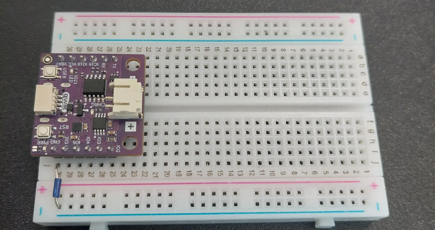
2. Build the ground rail
A short blue jumper takes j30 (the board's GND pin) down to the blue − rail. Everything in this circuit will find its way back to ground through that rail.
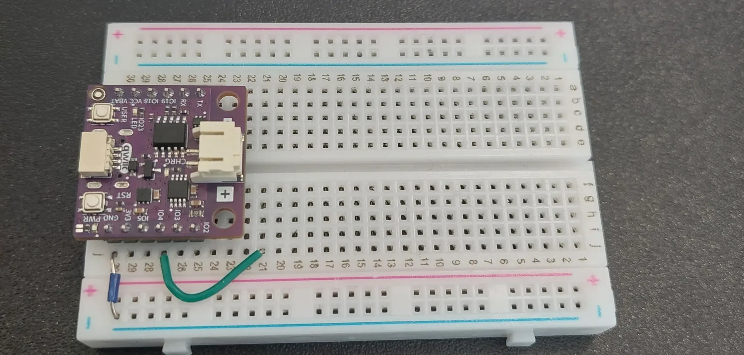
3. Run the green signal wire
The green jumper runs from j27 (the IO4 pin) out to j21, clear of the board.
4. Add the green LED's resistor
A 330 Ω resistor bridges h21 to h19, from the row the signal wire arrives in to the row the LED will sit in.
h21 and j21 are the same row, so the resistor and the jumper are connected even though they sit in different hole columns. Only the row number matters here; use whichever holes the legs reach comfortably.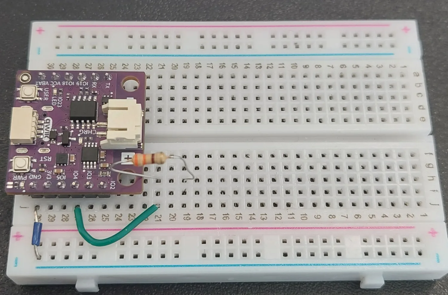
5. Press in the green LED
The green LED goes in with its long leg in i19, the row the resistor arrives in, and its short leg in i17.
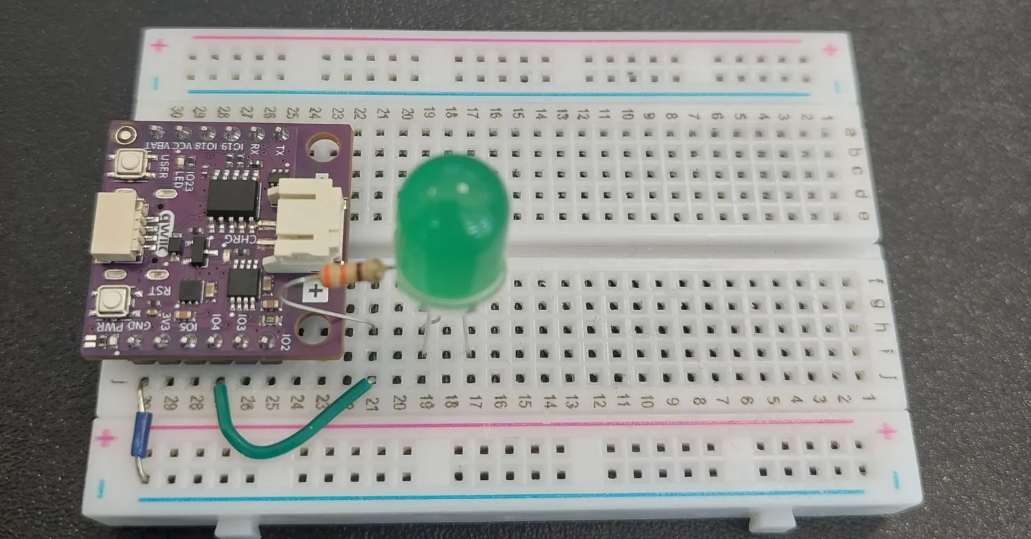
6. Ground the green LED
A blue jumper takes j17 down to the blue − rail, completing the first chain.
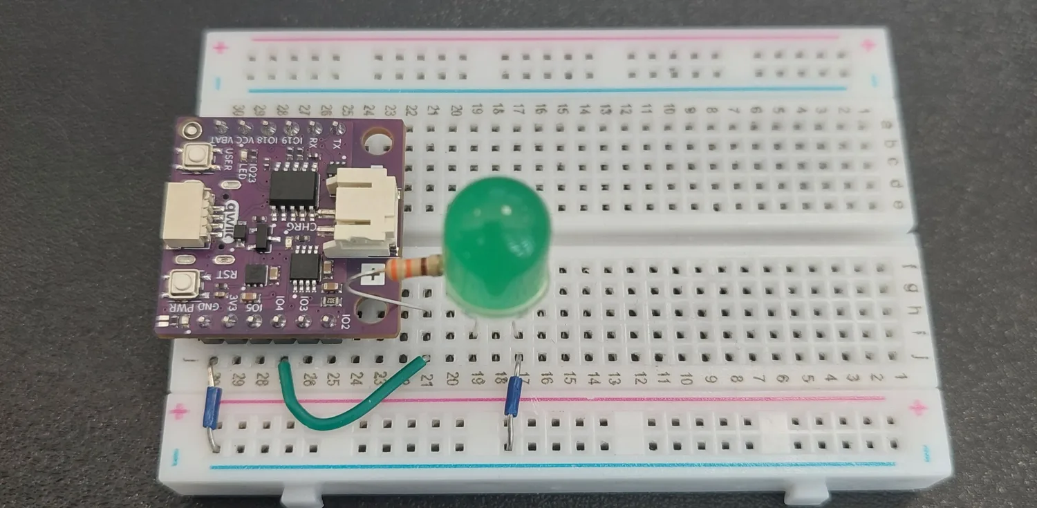
7. Run the orange signal wire
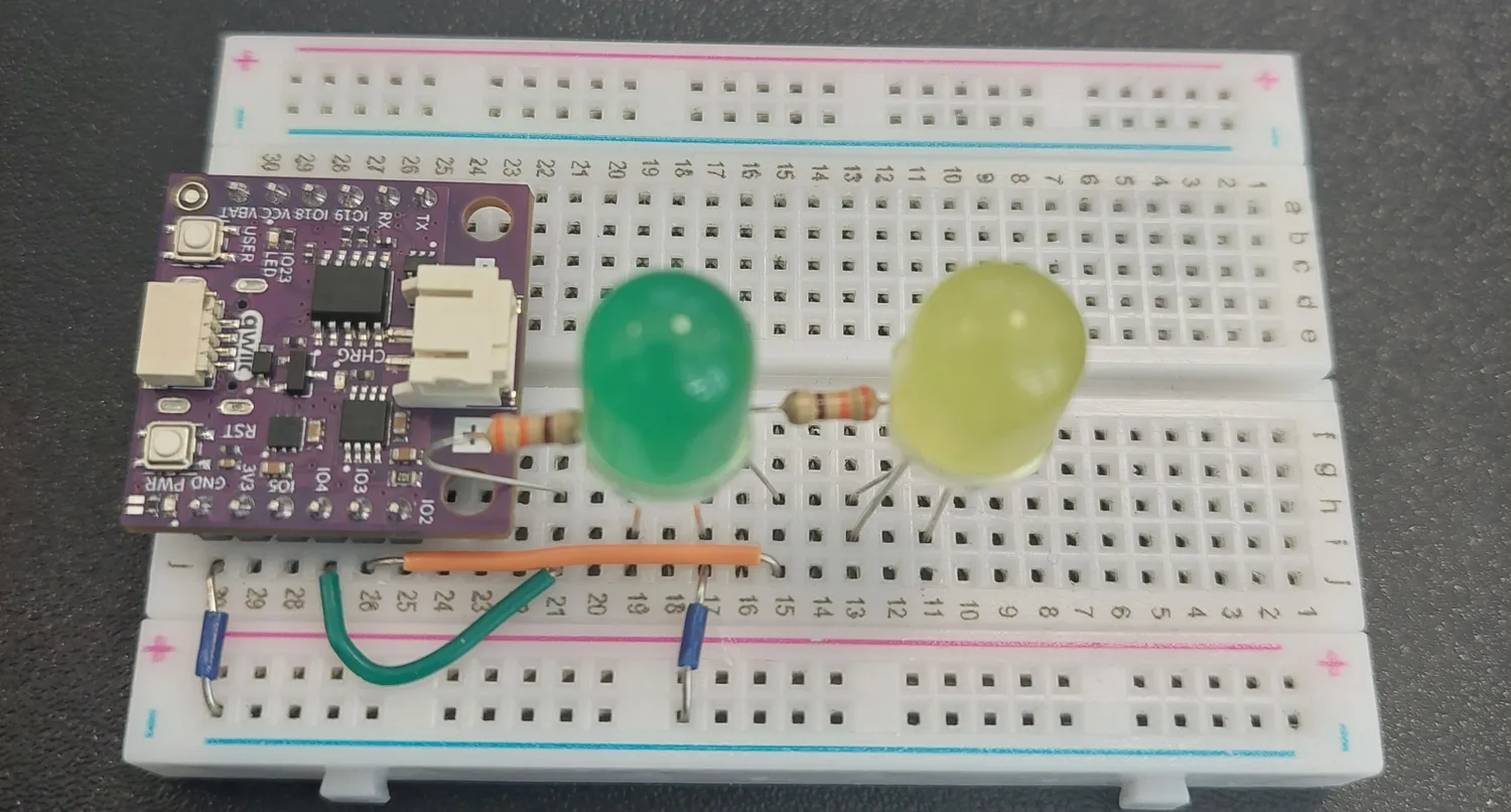
Now the same chain again, six rows further along. The orange jumper runs from j26 (the IO3 pin) out to j15.
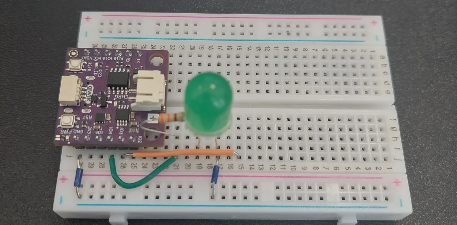
8. Add the orange LED's resistor
The second 330 Ω resistor bridges h15 to h13.
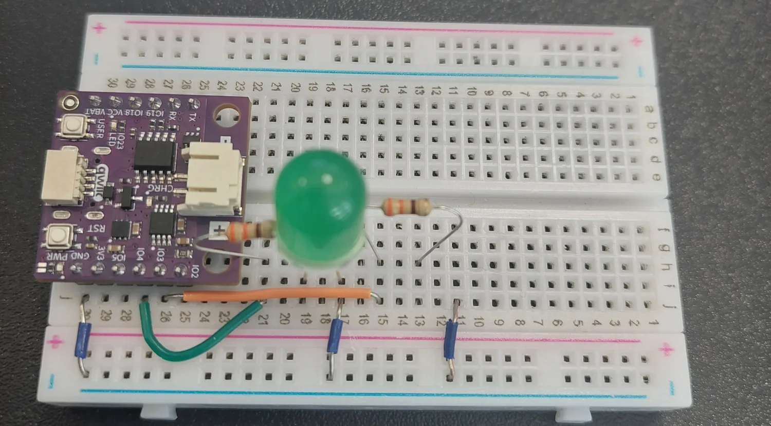
9. Press in the orange LED
Long leg in i13, short leg in i11.
10. Ground the orange LED
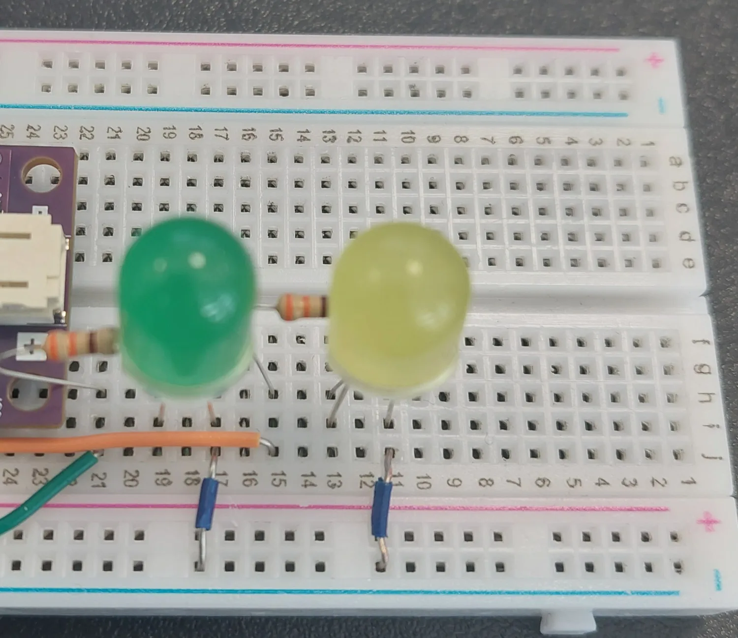
A blue jumper takes j11 down to the blue − rail.
11. Run the red signal wire
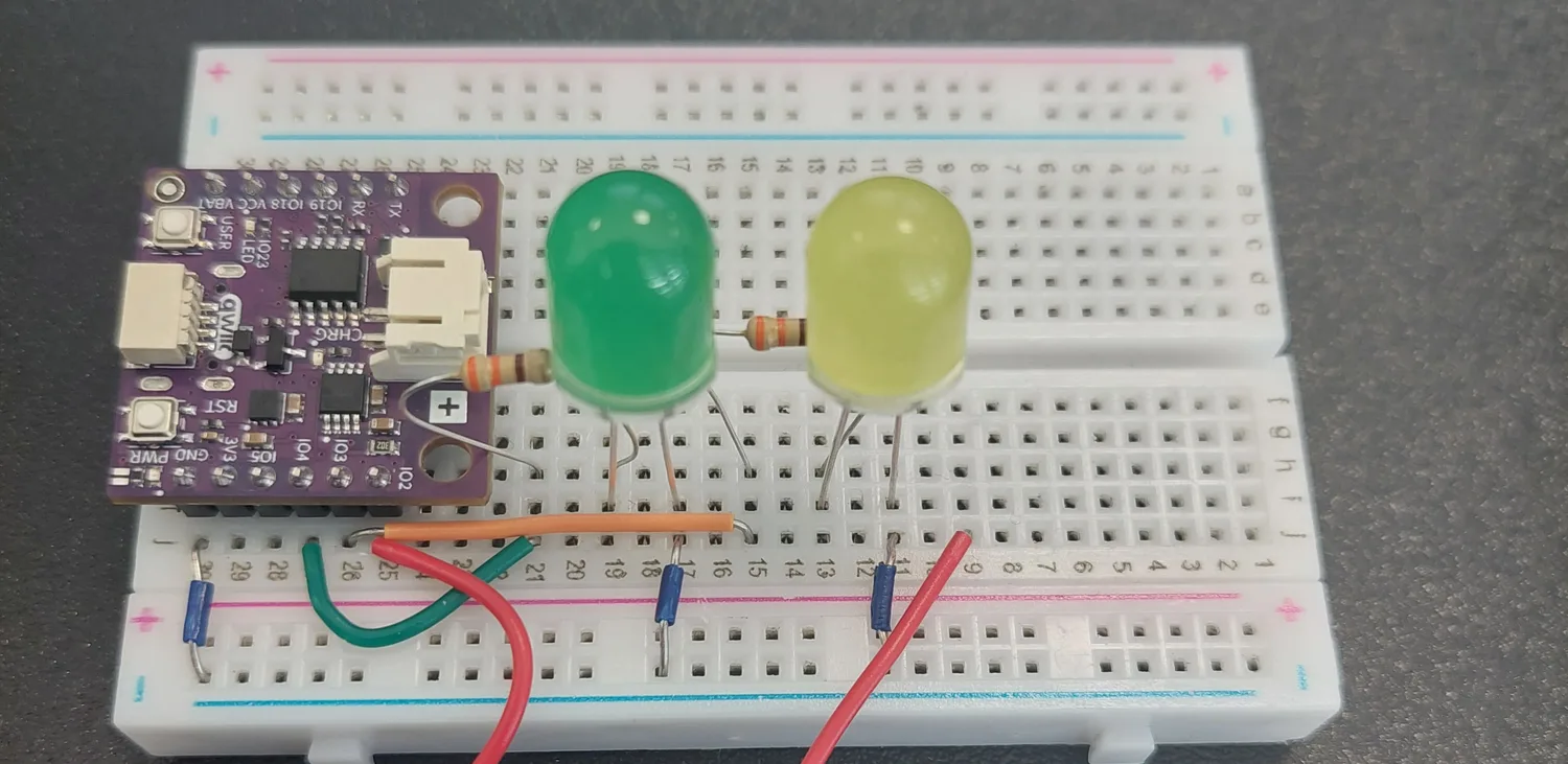
The red jumper runs from j25 (the IO2 pin) out to j9. It is a long wire and it takes the scenic route off the board and back; nothing is connected underneath, so the loop is harmless.
12. Add the red LED's resistor
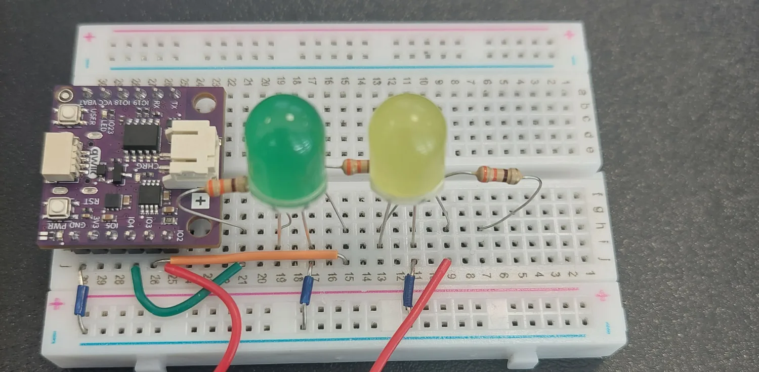
The third 330 Ω resistor bridges h9 to h7.
13. Press in the red LED
Long leg in i7, short leg in i5.
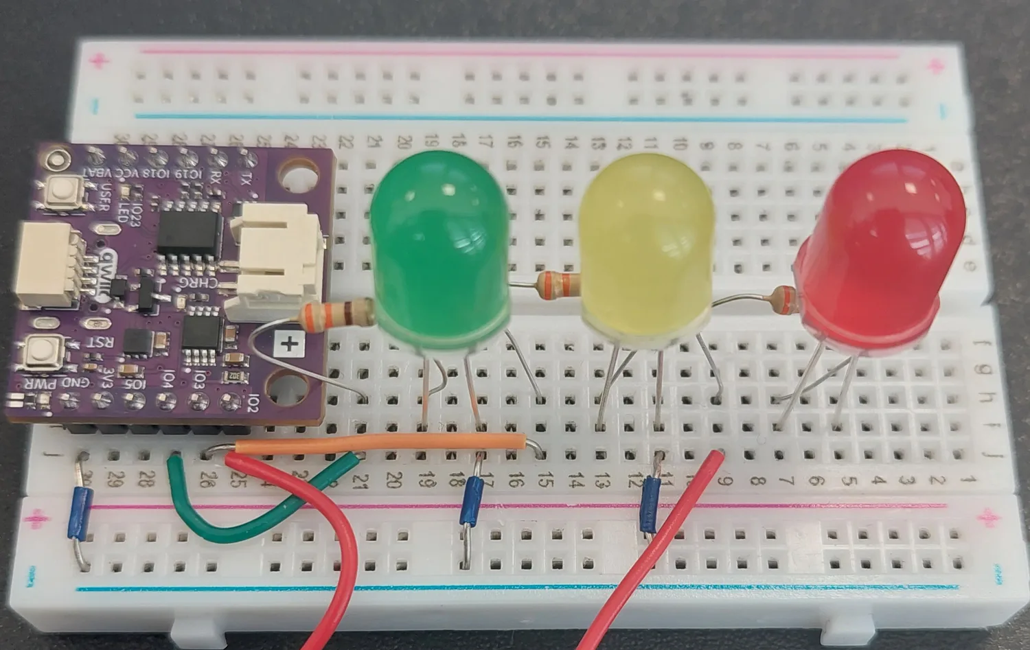
14. Ground the red LED
The last blue jumper takes j5 down to the blue − rail. The circuit is now complete.
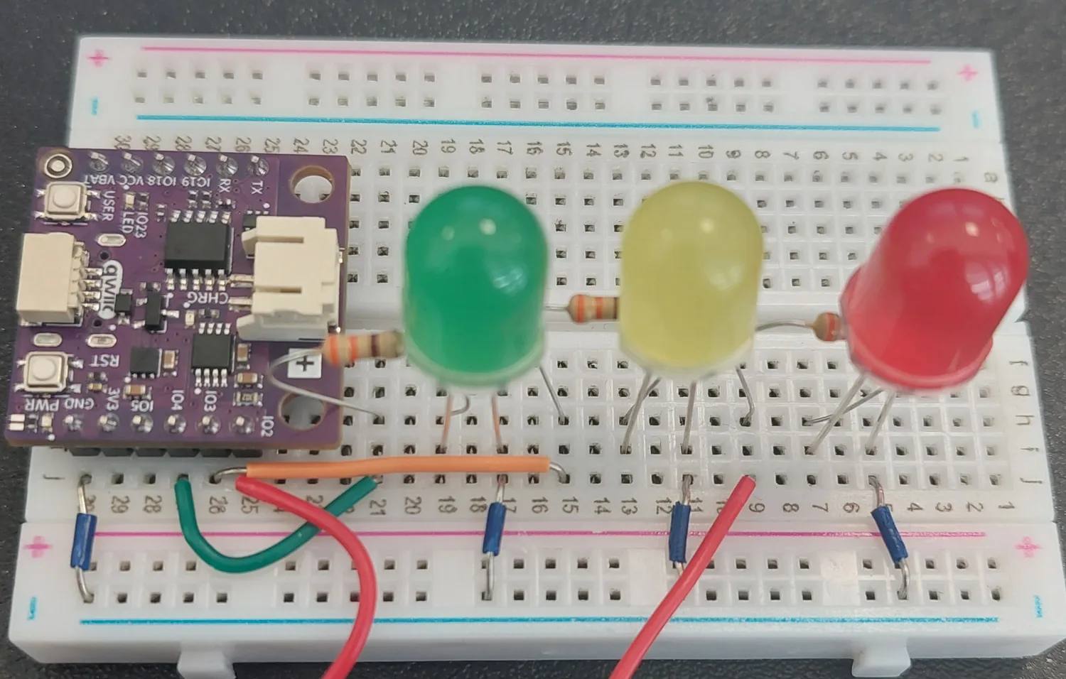
15. Connect the USB cable
Plug the USB-C cable into the board and into your computer.
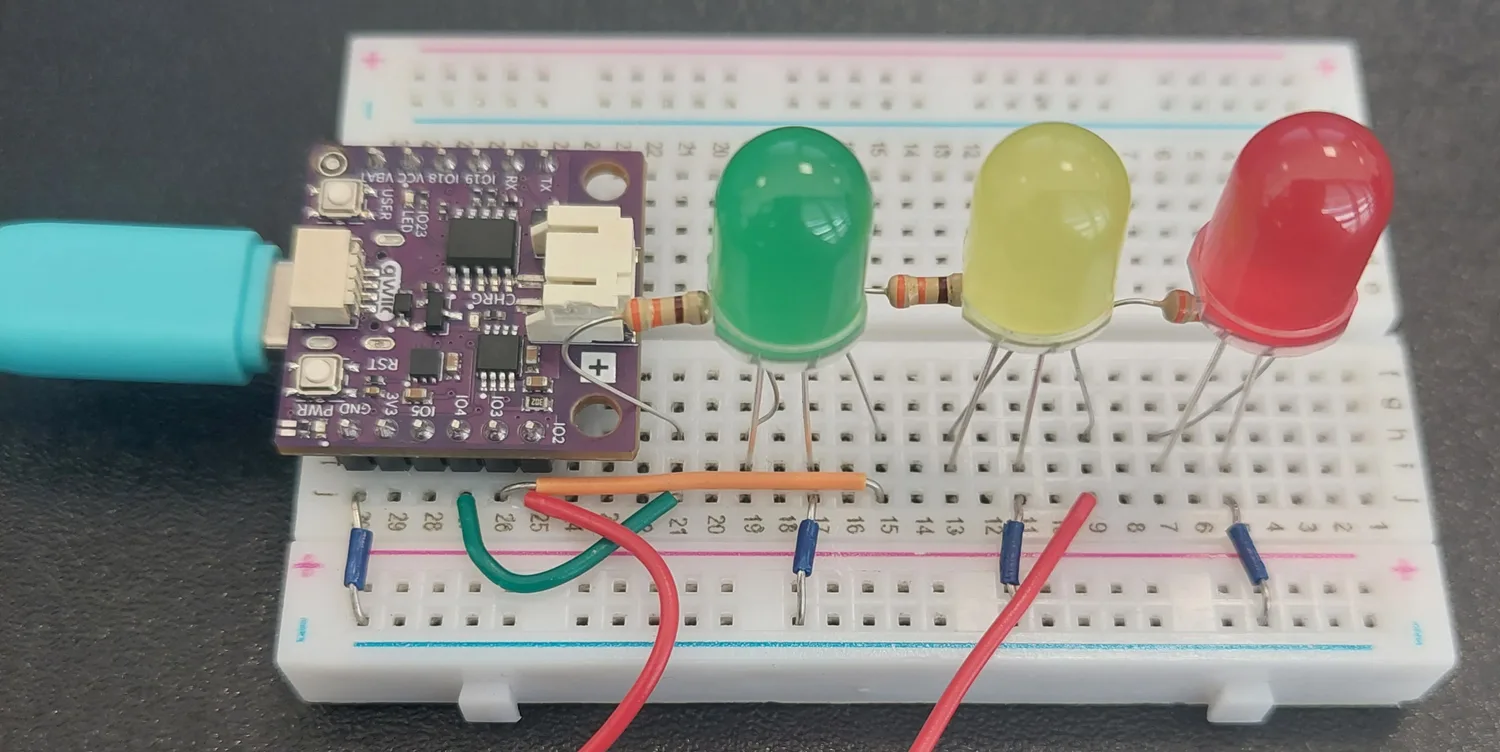
The whole circuit at a glance
| # | Part | From | To | What it does |
|---|---|---|---|---|
| 1 | Jumper | j30 (GND) | blue − rail | Makes the rail the shared ground |
| 2 | Jumper | j27 (IO4) | j21 | Green signal off the board |
| 3 | 330 Ω | h21 | h19 | Limits current, green channel |
| 4 | Green LED | i19 (long leg) | i17 | Green light |
| 5 | Jumper | j17 | blue − rail | Green LED back to ground |
| 6 | Jumper | j26 (IO3) | j15 | Orange signal off the board |
| 7 | 330 Ω | h15 | h13 | Limits current, orange channel |
| 8 | Orange LED | i13 (long leg) | i11 | Orange light |
| 9 | Jumper | j11 | blue − rail | Orange LED back to ground |
| 10 | Jumper | j25 (IO2) | j9 | Red signal off the board |
| 11 | 330 Ω | h9 | h7 | Limits current, red channel |
| 12 | Red LED | i7 (long leg) | i5 | Red light |
| 13 | Jumper | j5 | blue − rail | Red LED back to ground |
Read the board from the far end back and the LEDs come out red, orange, green, a real traffic light lying on its side.
How a state machine works
A finite state machine is a program that is always in exactly one of a small, fixed set of situations, and moves between them on some trigger. Here the situations are the five phases of the light, and the trigger is the clock.
The whole memory of the machine is three variables:
| Variable | Meaning |
|---|---|
state | Which phase we are in right now |
lastChange | The moment we entered that phase |
stateDuration | How long we mean to stay in it |
Every phase then does the same two things, and only those two: set the LEDs the way this phase wants them, and check whether its time is up. If it is, name the next phase, remember the current moment as the new starting point, and set the next duration. That pattern, repeated five times, is the entire program.
| Phase | LEDs lit | Duration |
|---|---|---|
GREEN | green | 5 s |
GREEN_BLINK | green, flashing every 0.4 s | 3 s |
ORANGE | orange | 2 s |
RED | red | 5 s |
RED_ORANGE | red and orange | 2 s |
One full lap is 17 seconds, and then it starts again. The red-and-orange phase is the warning used on many European roads that green is about to come.
The enum at the top is what makes the program readable. Without it the five phases would be the numbers 0 to 4, and a mistake would be very easy to make and very hard to spot. With it you write GREEN and RED, and the code reads almost like a description of the real thing.
Why millis() and not delay()
delay() stops the program dead. That is fine when a program has one thing to do, but look at the blinking green phase: the green LED has to flash on and off every 0.4 seconds while the three-second timer for the phase itself keeps running. Two clocks, at the same time, in the same block of code. delay() cannot do that, because whichever one you wait on, the other stops.
millis() returns the number of milliseconds since the board started running the current program. Instead of waiting, the program just looks at the clock and asks has enough time passed?:
if (now - lastChange >= stateDuration) {
The loop keeps spinning, thousands of times a second, and the answer is false almost every time. When it finally turns true, the phase changes. Nothing is ever blocked, so any number of timers can run side by side.
The two lines that keep the blink honest
When the program leaves GREEN for GREEN_BLINK it also does this:
greenOn = true;
lastBlink = now;
Without them, greenOn and lastBlink would still hold whatever they were left at on the previous lap. The green LED could enter the blinking phase already switched off, and the first flash would land at the wrong moment. Two lines to make the phase start from a known state, a small thing that is easy to leave out and annoying to track down afterwards.
Notice too that the GREEN_BLINK block never writes to LED_GREEN at the top the way the other phases do. It only turns the other two off. That is deliberate: while this phase is running the blinking code owns the green LED, and setting it HIGH on every pass would cancel the blink out.
Code
/**
 **************************************************
 *
 * @file        7.8_LED_Traffic_Light.ino
 * @brief       Project that simulates a traffic light with three LEDs, running through green, blinking green, orange,
 *              red and red together with orange, just like the lights on many European roads.
 *              It introduces the finite state machine, or FSM, which is a very common way of writing programs that move
 *              through a fixed series of steps without ever using delay() to wait.
 *              For details, connection diagram and more, check out the example documentation at: <link placeholder>
 * @author      Soldered
 ***************************************************
 */

/*
These are the variables to which we pass the numbers of pins that we had connected the three LEDs to.
The NULA board has a pin naming logic as follows: IO4, where 4 is the number that we give to the variable.
If you wish to use a different pin, make sure you are using a IO__ marked pin.

Remember that every one of these LEDs needs its own 330 Ohm resistor in series with it. That resistor limits how much
current flows, and without it an LED draws more than it is built for and can be damaged.
*/
const int LED_GREEN = 4;
const int LED_ORANGE = 3;
const int LED_RED = 2;

/*
An enum lets us give names to a fixed set of values. Without it we would have to remember that state 0 means green and
state 3 means red, and a mistake there would be very easy to make and very hard to spot. With it we can write GREEN and
RED instead, and the program reads almost like a description of a real traffic light.
Each of these names is one state that our traffic light can be in, and it can only ever be in one of them at a time.
*/
enum TrafficState {
  GREEN,
  GREEN_BLINK,
  ORANGE,
  RED,
  RED_ORANGE
};

/*
This variable holds the state we are in right now. Together with the two below it, it is the whole memory of our state
machine: "lastChange" remembers the moment we entered the current state, and "stateDuration" holds how long we mean to
stay in it. That is all a finite state machine needs: where am I, since when, and for how long.
*/
TrafficState state = GREEN;
unsigned long lastChange = 0;
unsigned long stateDuration = 0;

/*
These three variables are only used by the blinking green state. "greenOn" remembers whether the green LED is currently
lit, "blinkInterval" is how long it stays that way before flipping, and "lastBlink" remembers when it last flipped.
Feel free to experiment with the interval to make the blinking faster or slower.
*/
bool greenOn = true;
const unsigned long blinkInterval = 400;
unsigned long lastBlink = 0;

void setup() {

  /*
  Serial.begin() establishes serial communication between your board and your computer via a USB cable. We use it here
  to announce every change of state, which makes it much easier to follow what the state machine is doing.
  */
  Serial.begin(115200);

  /*
  pinMode() is a function that configures the specified pin to behave either as an input or in this case as an output.
  All three LEDs are things we write to, so all three pins go into OUTPUT mode.
  */
  pinMode(LED_GREEN, OUTPUT);
  pinMode(LED_ORANGE, OUTPUT);
  pinMode(LED_RED, OUTPUT);

  /*
  Here we set the starting state of our machine. millis() returns the number of milliseconds passed since the board
  began running the current program, so storing it now means "the green state began at this moment". The duration says
  we mean to stay green for 5000 milliseconds, which is five seconds.
  */
  state = GREEN;
  lastChange = millis();
  stateDuration = 5000;

  Serial.println("Traffic Light Example started!");
  Serial.println("State: GREEN");
}

void loop() {

  /*
  We read the clock once at the top of the loop and use that one value everywhere below, which keeps all the comparisons
  in this pass consistent with each other.
  */
  unsigned long now = millis();

  /*
  A switch statement is a tidier way of writing a long chain of if statements when we are comparing one variable against
  several fixed values. Here it lets us give each state its own block of code, and only the block belonging to the
  current state runs.
  Notice that every block does the same two things: it sets the LEDs the way this state wants them, and then it checks
  whether its time is up. If it is, it names the next state, remembers the current moment as the new starting point, and
  sets how long the next state should last. That pattern repeating five times is the entire state machine.
  The break at the end of each block tells the switch statement to stop there instead of falling through into the next
  one.
  */
  switch (state) {

    case GREEN:

      //Green on, everything else off.
      digitalWrite(LED_GREEN, HIGH);
      digitalWrite(LED_ORANGE, LOW);
      digitalWrite(LED_RED, LOW);

      //After five seconds, move on to the blinking green state and give it three seconds.
      if (now - lastChange >= stateDuration) {
        state = GREEN_BLINK;
        lastChange = now;
        stateDuration = 3000;

        /*
        Here we set the blinking up before we hand over to it. Without these two lines the blink would carry on from
        wherever it left off the previous time around the cycle, so the green LED could enter this state switched off
        and the first flash would come at the wrong moment.
        */
        greenOn = true;
        lastBlink = now;

        Serial.println("State: GREEN_BLINK");
      }
      break;

    case GREEN_BLINK:

      /*
      Here we leave the green LED alone, because the blinking below is what decides whether it is on or off. The other
      two stay off.
      */
      digitalWrite(LED_ORANGE, LOW);
      digitalWrite(LED_RED, LOW);

      /*
      This is the blinking itself. Every time the interval has passed we flip greenOn to its opposite value with the "!"
      operator and write the new value to the pin. Because this runs on the clock rather than on delay(), the state
      machine above keeps working the whole time the LED is blinking.
      */
      if (now - lastBlink >= blinkInterval) {
        greenOn = !greenOn;
        digitalWrite(LED_GREEN, greenOn);
        lastBlink = now;
      }

      //After three seconds of blinking, move on to orange and give it two seconds.
      if (now - lastChange >= stateDuration) {
        state = ORANGE;
        lastChange = now;
        stateDuration = 2000;
        Serial.println("State: ORANGE");
      }
      break;

    case ORANGE:

      //Orange on, everything else off.
      digitalWrite(LED_GREEN, LOW);
      digitalWrite(LED_ORANGE, HIGH);
      digitalWrite(LED_RED, LOW);

      //After two seconds, move on to red and give it five seconds.
      if (now - lastChange >= stateDuration) {
        state = RED;
        lastChange = now;
        stateDuration = 5000;
        Serial.println("State: RED");
      }
      break;

    case RED:

      //Red on, everything else off.
      digitalWrite(LED_GREEN, LOW);
      digitalWrite(LED_ORANGE, LOW);
      digitalWrite(LED_RED, HIGH);

      //After five seconds, move on to red together with orange and give it two seconds.
      if (now - lastChange >= stateDuration) {
        state = RED_ORANGE;
        lastChange = now;
        stateDuration = 2000;
        Serial.println("State: RED_ORANGE");
      }
      break;

    case RED_ORANGE:

      /*
      Red and orange lit at the same time, which on many European traffic lights is the warning that green is coming.
      */
      digitalWrite(LED_GREEN, LOW);
      digitalWrite(LED_ORANGE, HIGH);
      digitalWrite(LED_RED, HIGH);

      //After two seconds we are back at the start, and the whole cycle begins again.
      if (now - lastChange >= stateDuration) {
        state = GREEN;
        lastChange = now;
        stateDuration = 5000;
        Serial.println("State: GREEN");
      }
      break;
  }
}
What you should see
The three LEDs cycle continuously, and the whole lap takes 17 seconds.
Four of the five phases are steady, and the one in the middle is not: during the blinking green the LED flashes four times, on for 0.4 s and off for 0.4 s. For half of those three seconds every LED on the board is dark, which is worth knowing before you decide something has stopped working. The only phase with two LEDs lit at once is the red-and-orange one at the end.
In the Serial Monitor
Unlike most of the projects in this kit, this sketch talks. Open the Serial Monitor at 115200 baud and every phase change is announced as it happens, so you can follow the state machine even when you are not watching the LEDs. Straight after a reset you will see:
Traffic Light Example started!
State: GREEN
State: GREEN_BLINK
State: ORANGE
State: RED
State: RED_ORANGE
State: GREEN
and then those same five lines over and over.

The gaps between the lines are the durations themselves: five seconds after State: RED appears, State: RED_ORANGE follows it. That makes the Monitor a useful test on its own: if these lines keep scrolling at the right pace but the LEDs are doing nothing, the program is fine and the fault is in the wiring.
If one colour never lights, that LED's own chain is at fault, and the other two prove the board and the code are fine. Check its polarity first, then that its resistor really does bridge two different rows. If nothing lights at all, check the j30 ground wire: without it, none of the three chains has a way back.
Full example
Check out the full example code on the link below:
7.8_LED_Traffic_Light.ino
Traffic light simulation using the NULA MINI and three LEDs. Demonstrates finite state machines, non-blocking timing with millis(), and driving several outputs from one timed sequence.