7.6 Morse Code Transmitter
Every project so far has been a one-way conversation: the board talks, you watch. This one listens. You type a message into the Serial Monitor, the board looks up each letter in a table of dots and dashes, and blinks it out on a single LED, using the same code that carried messages down telegraph wires for a century before anyone had a computer.
The circuit is the simplest one in the kit: one LED, one resistor, three wires. All of the interest is in the program.
In this documentation you will learn:
- How to read text you type into the Serial Monitor with
Serial.readStringUntil() - What a lookup table is, and why it beats a long chain of
ifstatements - How to bundle two values together into one thing of your own with a
struct - How to write your own functions to keep a longer program readable
- How Morse code measures everything in units instead of milliseconds
Hardware required:
- 1x Soldered NULA MINI board
- 1x Breadboard
- 1x LED (any colour)
- 1x 330 Ω resistor (orange-orange-brown)
- 3x Jumper wires
- 1x USB-C cable
Putting the components together
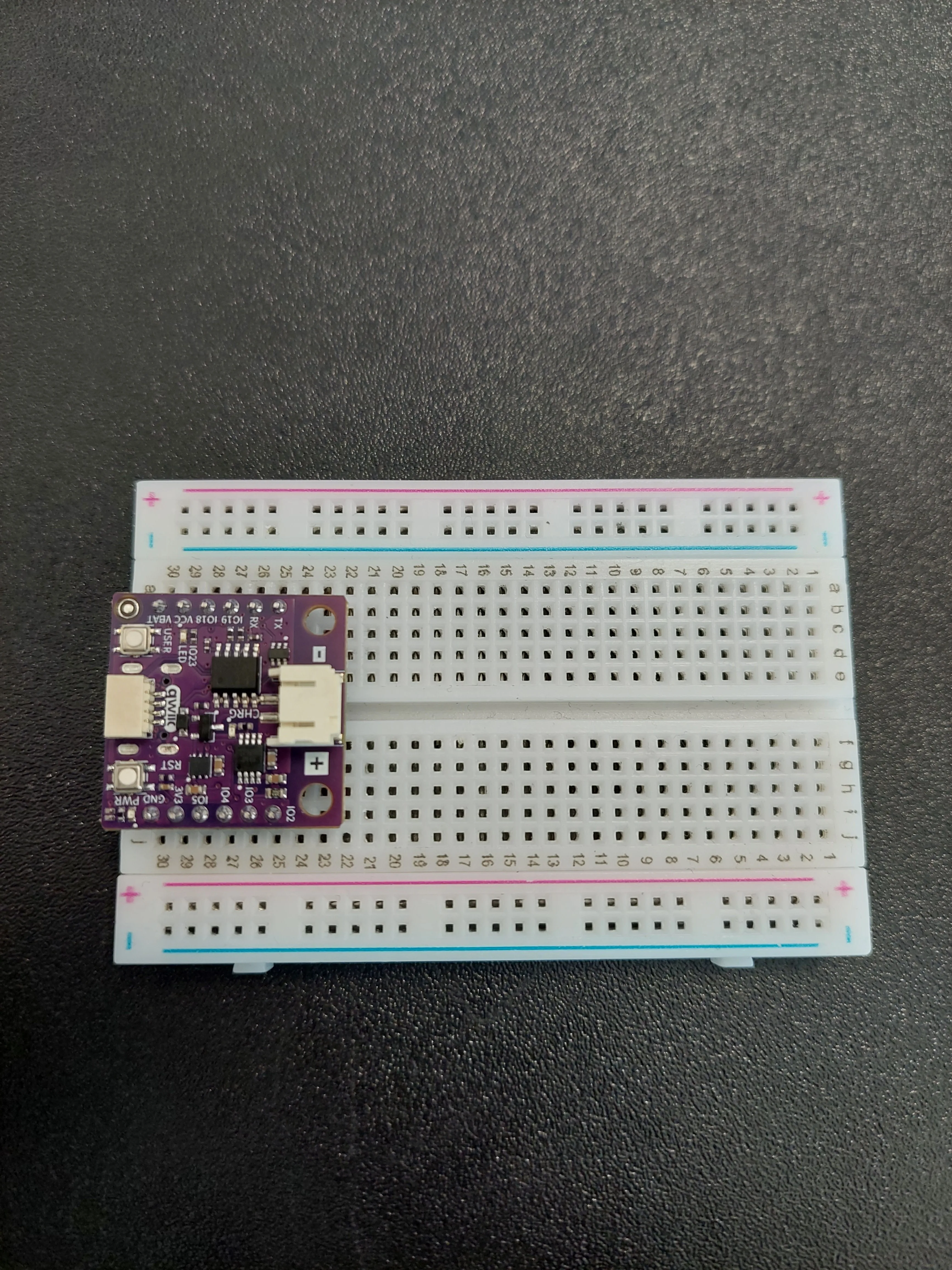
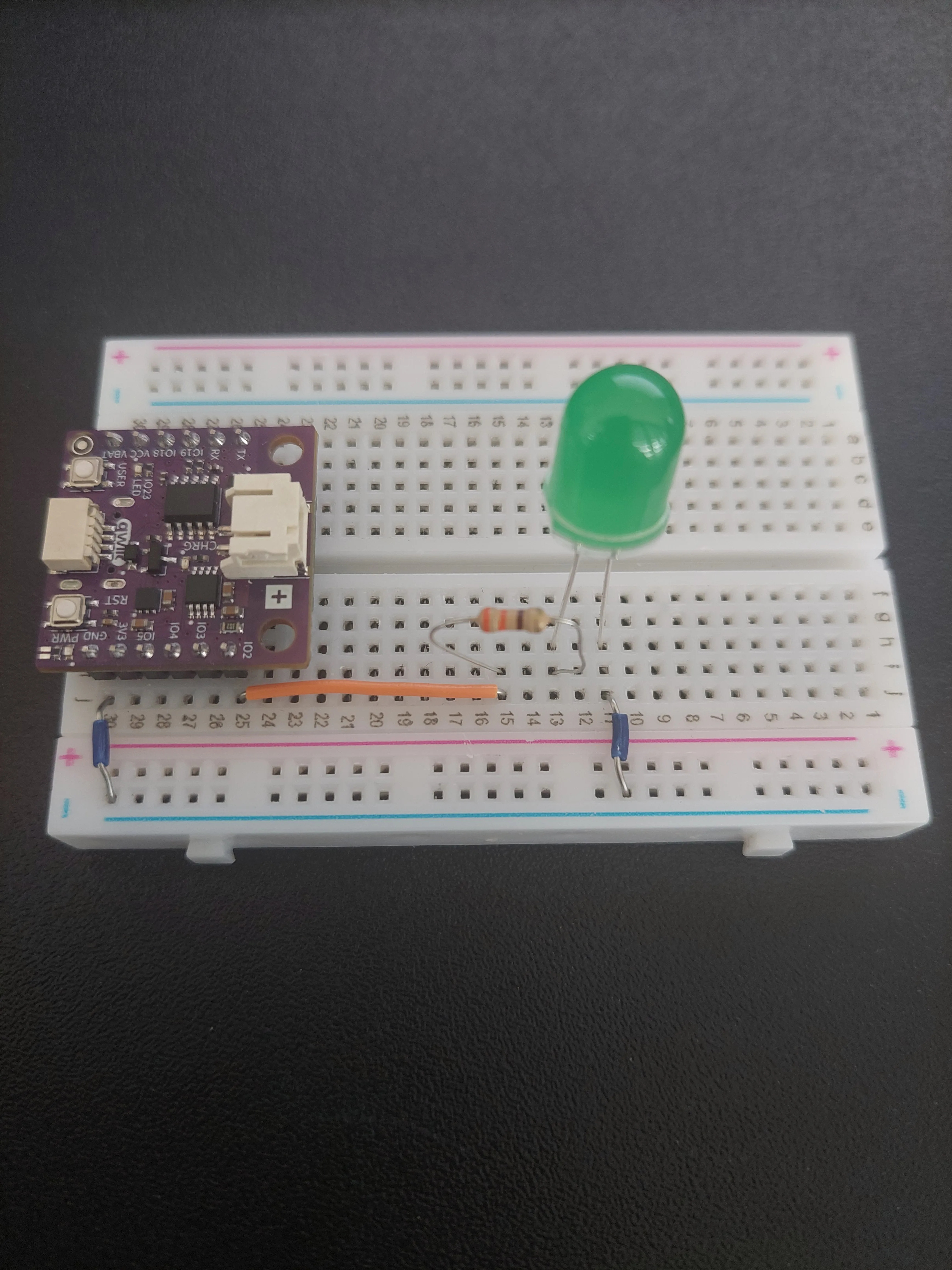
This project uses a single pin: IO2, which sits in row 25 on the f–j side. The board body covers columns f–i, so j25 and j30 are the only holes you can actually get a wire into at that end. Everything else happens further along the same f–j side, well clear of the board.
IO2 on the f–j side but TX on the a–e side. Count the rows on the same side you are plugging into.1. Insert the NULA MINI board on the breadboard
Push the board into one end of the breadboard so that its two rows of pins sit on either side of the centre channel, with the chip facing down. It should occupy rows 25 to 30.
2. Make the ground bus and bring IO2 out
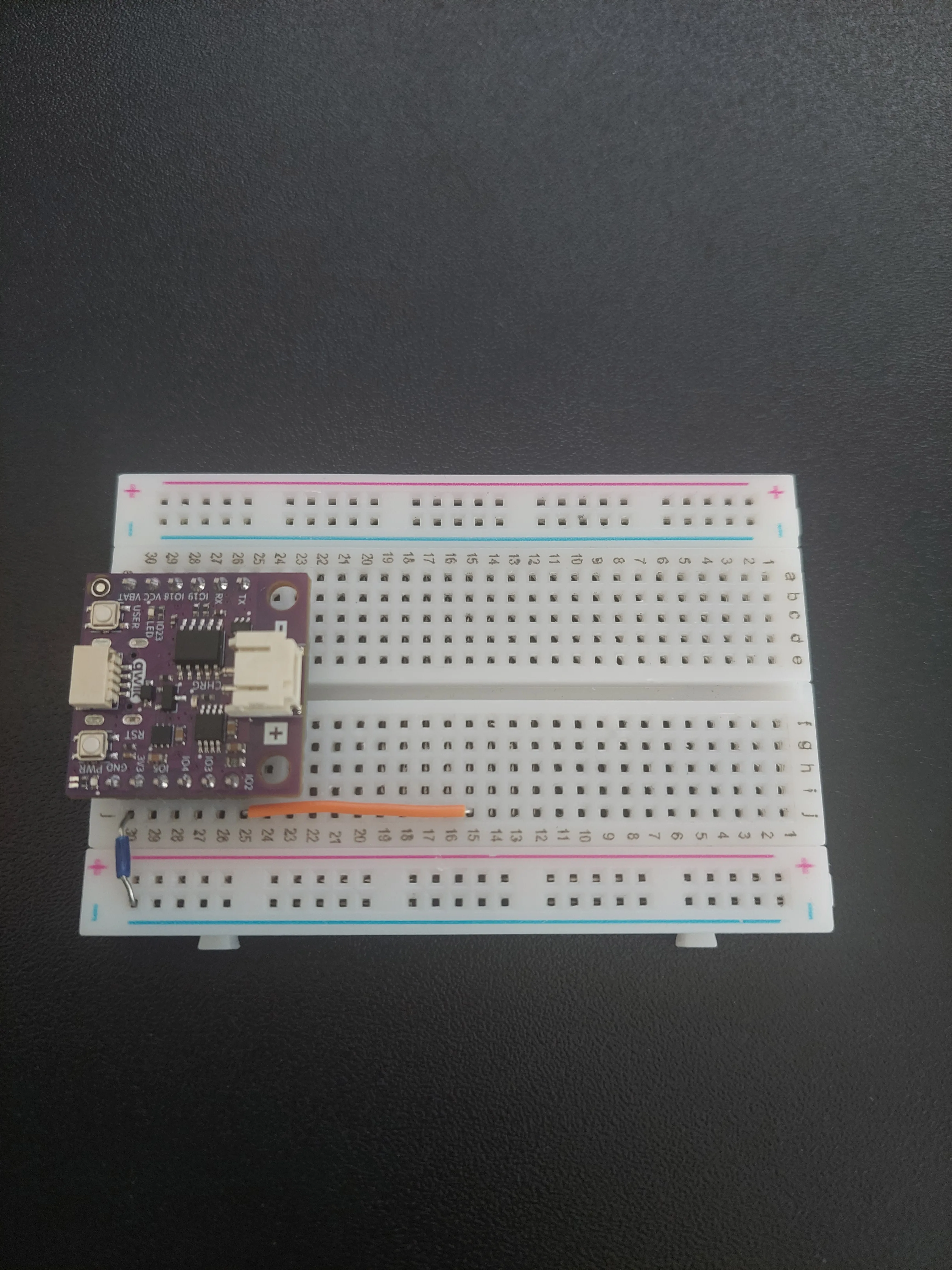
Two wires go in here, because they are the two ends of the circuit you are about to build between them.
First, a jumper from j30 (GND) across to the blue − rail. That rail becomes the shared ground line, exactly as in every other project in this kit.
Then a jumper from j25 (IO2) along to j15. This carries the Morse signal out from under the board to a row you can actually reach.
3. Add the 330 Ω resistor
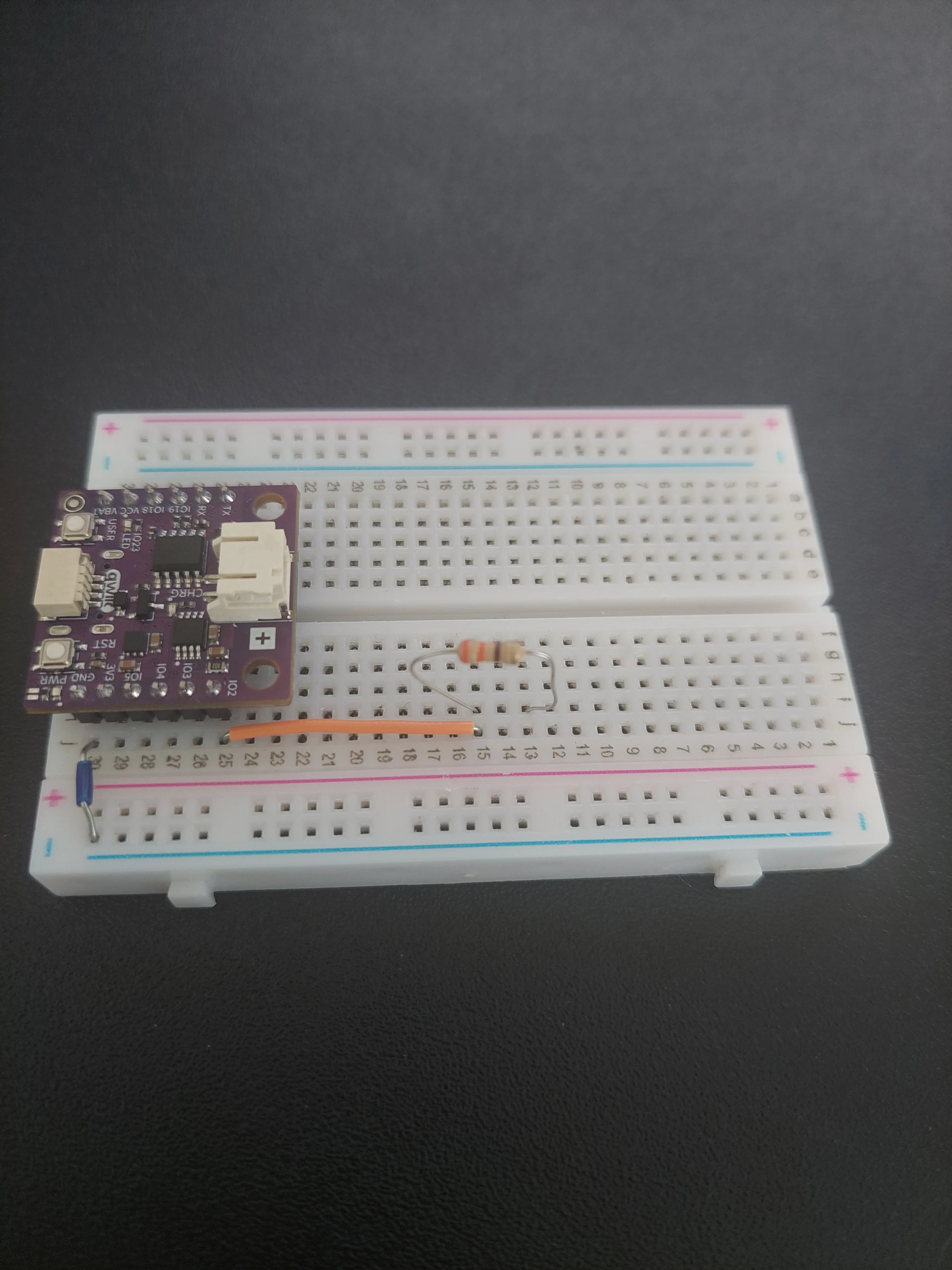
Push the resistor in so that it bridges row 15 and row 13. Its bands read orange-orange-brown. A resistor has no polarity, so either way round is correct.
4. Add the LED
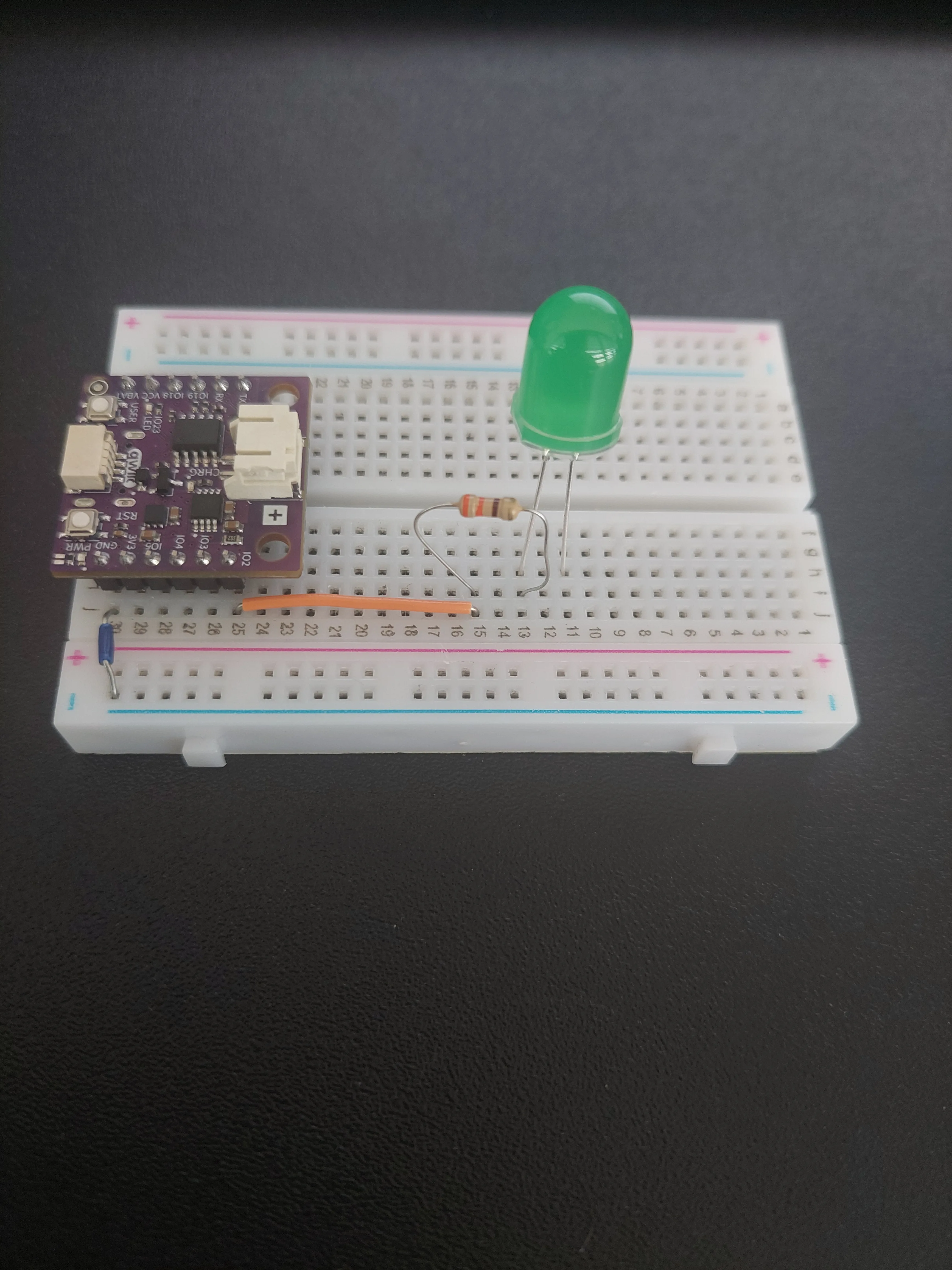
The LED does have a polarity. Its longer leg is the anode, and that one goes into row 13, alongside the resistor. The shorter leg goes into row 11.
5. Connect the LED to ground
One last jumper, from j11 to the blue − rail. That closes the loop: IO2 → resistor → LED → ground.
6. Connect the board to your computer
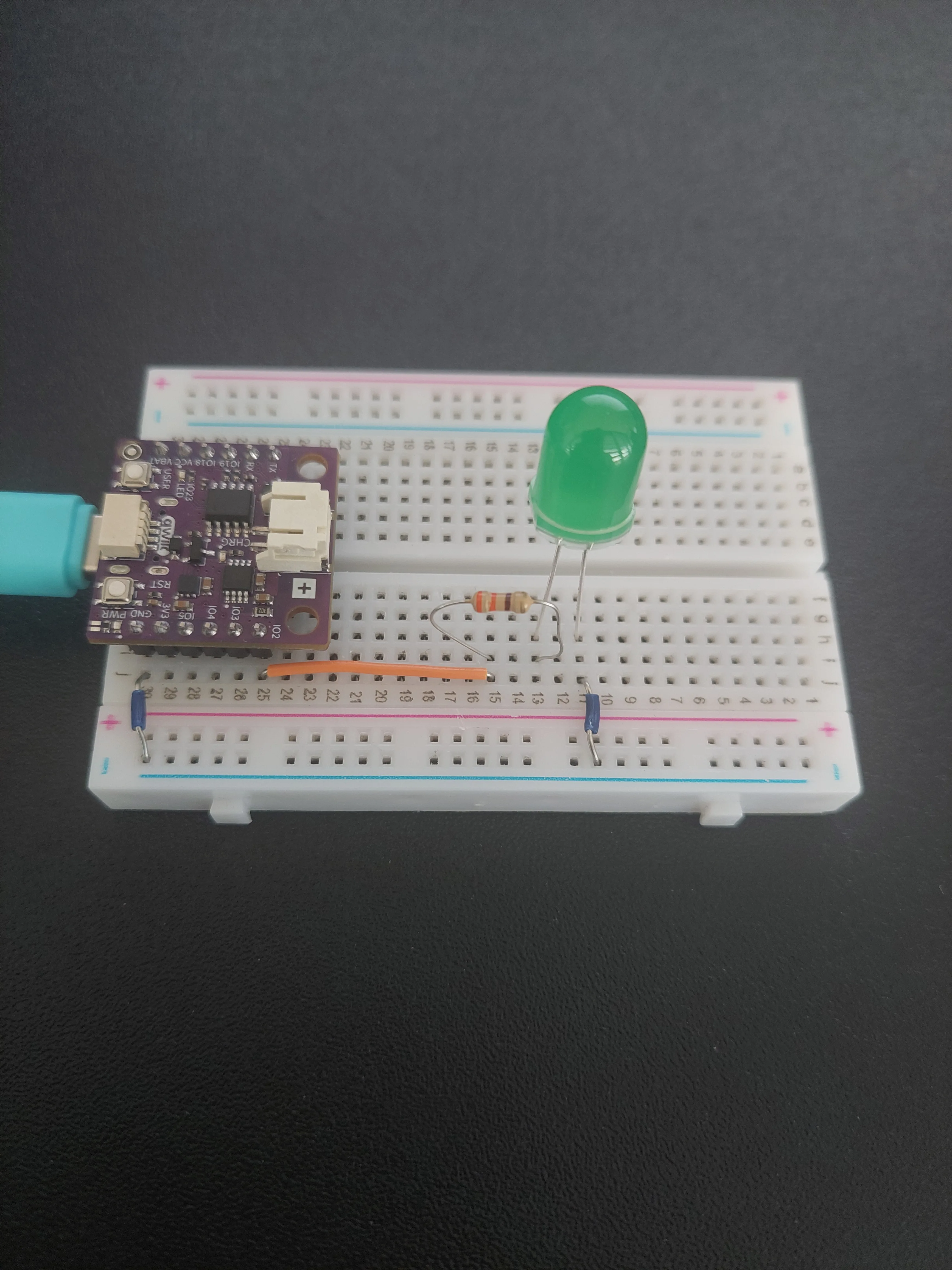
Plug the USB-C cable into the board and into your computer. The purple PWR LED comes on; the green LED stays dark, because nothing has been typed yet.
How the circuit works
Only three rows matter, and they sit in series, so the current has exactly one path to follow:
| Row | What is in it |
|---|---|
| 15 | the jumper from IO2, and one leg of the resistor |
| 13 | the resistor's other leg, and the LED's long leg |
| 11 | the LED's short leg, and the jumper to the − rail |
All five holes in a row are joined inside the breadboard, which is what lets two different components meet in one row without touching each other. It is also why the exact row numbers do not matter: any three free rows work, as long as the order IO2 → resistor → LED → ground is preserved.
When the sketch calls digitalWrite(LED_PIN, HIGH), IO2 is driven to 3.3 V, current flows down that chain and the LED lights. LOW puts the pin back to 0 V and the LED goes out. That is the whole of the hardware. Everything else on this page is program.
How Morse code works
Morse does not measure its signals in milliseconds. It measures everything in units, where one unit is the length of a dot, and every other duration is a multiple of it:
| Length | |
|---|---|
| Dot | 1 unit of light |
| Dash | 3 units of light |
| Gap between the dots and dashes within a letter | 1 unit of silence |
| Gap between letters | 3 units of silence |
| Gap between words | 7 units of silence |
That is why the sketch contains only one real number. DOT_DURATION is 300 ms and everything else is calculated from it:
const int DOT_DURATION = 300;
const int DASH_DURATION = DOT_DURATION * 3;
const int SYMBOL_GAP = DOT_DURATION;
const int LETTER_GAP = DOT_DURATION * 3;
const int WORD_GAP = DOT_DURATION * 7;
Change DOT_DURATION on its own and the whole transmission speeds up or slows down while staying correct Morse. Set it to 100 and you get a fast operator; set it to 600 and you get a slow one.
The table of letters
The sketch needs to turn a character into a string of dots and dashes. It could do that with twenty-six if statements, but instead it uses a lookup table: a list it searches through.
To build that list it first needs a way to keep a letter and its code together as a single item, and that is what a struct is for:
struct MorseEntry { char letter; const char *code; };
Now morseTable can be an array of those, one entry per character. Adding a character of your own means adding one line to the table and changing nothing else. That is the whole advantage over a chain of if statements.
getMorseCode() is the function that does the looking up. It walks the table from the start and returns as soon as it finds a match, and toupper() at the top means typing sos works just as well as SOS. If the character is not in the table at all it returns empty text, which the transmitting function simply skips over.
const int MORSE_COUNT = sizeof(morseTable) / sizeof(MorseEntry); works out how many entries the table has instead of counting them by hand: the size of the whole table divided by the size of one entry. Written this way, the number stays correct after you add a character of your own.Two loops over the same text
transmitText() walks through your message twice. The first pass prints the translation to the Serial Monitor so you can read along, and the second pass blinks the same thing out on the LED. Splitting it in two is what lets the whole translation appear on screen immediately, before the LED has finished spelling out even the first letter.
In the blinking pass, a space is not blinked at all. It is a pause. When the loop finds one it waits a word gap and uses continue to skip the rest of that pass. Every other character has its symbols blinked one by one, and then the loop waits a letter gap before moving on.
The gaps are slightly generous
There is one thing worth knowing before you start counting blinks. blinkSymbol() ends every symbol with one unit of silence, and then transmitText() adds LETTER_GAP on top of it. So the gap you actually see between two letters is 1 + 3 = 4 units, not 3, and between two words it is 1 + 3 + 7 = 11 units, not 7.
Real Morse replaces the symbol gap rather than adding to it. The difference does not make the message wrong. Every dot and dash is exactly the right length, and the gaps are still clearly distinguishable from one another; the transmission is just a little slower than the standard. It is worth knowing so that what you count matches what you expect.
Code
Below is the full example code for this project:
/**
 **************************************************
 *
 * @file        7.6_Morse_code_transmitter.ino
 * @brief       Project that turns text you type into the Serial Monitor into Morse code and blinks it out on an LED.
 *              Morse code represents every letter as a pattern of short and long signals, called dots and dashes.
 *              Along the way the example introduces three new ideas: reading text from the Serial Monitor, storing a
 *              lookup table, and writing your own functions to keep a longer program readable.
 *              For details, connection diagram and more, check out the example documentation at: <link placeholder>
 * @author      Soldered
 ***************************************************
 */

/*
This is a variable to which we pass the number of pin that we had connected the LED to.
The NULA board has a pin naming logic as follows: IO2, where 2 is the number that we give to the variable.
If you wish to use a different pin, make sure you are using a IO__ marked pin.

Remember that the LED needs a 330 Ohm resistor in series with it. That resistor limits how much current flows, and
without it the LED draws more than either it or the pin is built for, so both can be damaged.
*/
const int LED_PIN = 2;

/*
Morse code does not measure its signals in milliseconds but in units, and every other duration is a multiple of one
unit. That is why only the first value below is a real number and the rest are calculated from it: change DOT_DURATION
alone and the whole transmission speeds up or slows down while staying correct Morse.
The standard proportions are a dash three units long, one unit of silence between the dots and dashes of a letter,
three units between letters, and seven units between words.
*/
const int DOT_DURATION = 300;
const int DASH_DURATION = DOT_DURATION * 3;
const int SYMBOL_GAP = DOT_DURATION;
const int LETTER_GAP = DOT_DURATION * 3;
const int WORD_GAP = DOT_DURATION * 7;

/*
A struct lets us bundle several values into one thing of our own making. Here each MorseEntry holds a character and the
dots and dashes that stand for it, so the two always travel together.
*/
struct MorseEntry { char letter; const char *code; };

/*
This is our lookup table: an array of the structs above, one for every character we can send. A lookup table is simply
a list we search through instead of writing out dozens of if statements, and it has the nice property that adding a new
character means adding one line here and changing nothing else.
The last entry maps a space to a space, which is how we recognise the gap between two words.
*/
const MorseEntry morseTable[] = {
  {'A', ".-"},   {'B', "-..."}, {'C', "-.-."}, {'D', "-.."},  {'E', "."},
  {'F', "..-."}, {'G', "--."},  {'H', "...."}, {'I', ".."},   {'J', ".---"},
  {'K', "-.-"},  {'L', ".-.."}, {'M', "--"},   {'N', "-."},   {'O', "---"},
  {'P', ".--."}, {'Q', "--.-"}, {'R', ".-."},  {'S', "..."},  {'T', "-"},
  {'U', "..-"},  {'V', "...-"}, {'W', ".--"},  {'X', "-..-"}, {'Y', "-.--"},
  {'Z', "--.."},
  {'1', ".----"},{'2', "..---"},{'3', "...--"},{'4', "....-"},{'5', "....."},
  {'6', "-...."},{'7', "--..."},{'8', "---.."},{'9', "----."},{'0', "-----"},
  {' ', " "}
};

/*
Here we work out how many entries the table above actually has, instead of counting them by hand. sizeof() tells us how
much memory something takes up, so the size of the whole table divided by the size of one entry gives us the number of
entries. Written this way the number stays correct even after you add a character of your own.
*/
const int MORSE_COUNT = sizeof(morseTable) / sizeof(MorseEntry);

/*
This is a function we wrote ourselves. Up to now our sketches only used setup() and loop() plus functions from
libraries, but as a program grows it helps to give a job a name of its own.
This one takes a character and hands back the dots and dashes that stand for it. toupper() turns a lowercase letter
into an uppercase one, so that typing "sos" works just as well as "SOS". Then we walk through the table from the start
and return as soon as we find a match. If the character is not in the table at all we return empty text, which the
transmitting function below simply skips over.
*/
const char* getMorseCode(char c) {
  c = toupper(c);
  for (int i = 0; i < MORSE_COUNT; i++)
    if (morseTable[i].letter == c) return morseTable[i].code;
  return "";
}

/*
This function blinks out a single dot or dash. It picks the right duration for the symbol it was given, switches the
LED on for exactly that long, and then switches it off and waits one more unit, which is the silence that separates one
symbol from the next.
*/
void blinkSymbol(char symbol) {
  int duration;
  if(symbol=='.'){
    duration=DOT_DURATION;
  }
  else{
    duration=DASH_DURATION;
  }
  digitalWrite(LED_PIN, HIGH);
  delay(duration);
  digitalWrite(LED_PIN, LOW);
  delay(SYMBOL_GAP);
}

/*
This function transmits a whole piece of text. It does the work twice over: first it prints the translation to the
Serial Monitor so you can read along, and then it blinks the same thing out on the LED.
The "&" in the parameter means the text is handed over without being copied, which saves memory on longer messages.
*/
void transmitText(const String &text) {
  Serial.println("\n--- TRANSMITTING ---");
  Serial.print("Text:   "); Serial.println(text);
  Serial.print("Morse:  ");

  /*
  This first loop walks through the text one character at a time. length() tells us how many characters there are, and
  text[i] gives us the one at position i, counting from zero. For each of them we look up the code and print it.
  */
  for (unsigned int i = 0; i < text.length(); i++) {
    const char *code = getMorseCode(text[i]);
    Serial.print(code);
    Serial.print(" ");
  }
  Serial.println("\n--------------------");

  /*
  This second loop walks through the very same text again, but this time it blinks instead of printing.
  A space is not blinked at all, it is a pause, so when we find one we wait a word gap and skip the rest of this pass
  with continue. Otherwise the inner loop blinks the symbols of the letter one by one, and once they are done we wait a
  letter gap before moving on to the next letter.
  */
  for (unsigned int i = 0; i < text.length(); i++) {
    const char *code = getMorseCode(text[i]);
    if (*code == ' ') {
      delay(WORD_GAP);
      continue;
    }
    for (int j = 0; code[j]; j++){
      blinkSymbol(code[j]);
    }
    delay(LETTER_GAP);
  }

  Serial.println("\nTransmission complete!\n");
}

void setup() {

  /*
  Serial.begin() establishes serial communication between your board and your computer via a USB cable. In this example
  we use it in both directions for the first time: to print messages out, and to read the text you type in.
  */
  Serial.begin(115200);

  /*
  pinMode() is a function that configures the specified pin to behave either as an input or in this case as an output.
  As our pin needs to turn on the LED, we will put the pin in OUTPUT mode.
  */
  pinMode(LED_PIN, OUTPUT);

  //Invite the user to type something. Type into the box at the top of the Serial Monitor and press Enter.
  Serial.println("Enter text to send via Morse code:");
}

void loop() {

  /*
  Serial.available() tells us how many characters have arrived from the computer and are waiting to be read. It returns
  zero when nothing has been typed, so this if statement is how we do nothing at all until the user sends us something.
  */
  if (Serial.available()) {

    /*
    readStringUntil() collects the arriving characters into text and stops at the character we name, in this case the
    newline that the Serial Monitor sends when you press Enter.
    trim() then removes any stray spaces or leftover line endings from both ends, which is worth doing because
    different systems end their lines slightly differently.
    */
    String input = Serial.readStringUntil('\n');
    input.trim();

    /*
    Finally we check that something is actually left after trimming, so that pressing Enter on an empty line does not
    start a transmission, and hand the text over to our own function above.
    */
    if (input.length() > 0) transmitText(input);
  }
}
What you should see
Upload the sketch, then open the Serial Monitor and set the baud rate to 115200. The board greets you:
Enter text to send via Morse code:
Type a message into the input box at the top of the Serial Monitor and press Enter. Type it in lowercase, as sos, to see something useful:
--- TRANSMITTING ---
Text:   sos
Morse:  ... --- ...
--------------------

Transmission complete!
The Text: line echoes back exactly what you typed, lowercase and all, but the Morse: line is correct anyway. That is toupper() inside getMorseCode() doing its work: the table only holds capital letters, and every character is converted before it is looked up. The translation appears at once, all of it, and only then does the LED start blinking.

Three things in that window matter as much as the text itself. The 115200 baud selector on the right has to match the Serial.begin(115200) in the sketch, or the output arrives as unreadable rubbish. The New Line dropdown beside it decides what gets sent when you press Enter. And the input box across the top names the board and the port it will send to, Soldered NULA Mini ESP32C6 on COM6 here, though your own port will almost certainly have a different name.
readStringUntil('\n') waits for the newline character it sends, and on No Line Ending it has to wait out its one-second timeout instead. The message still transmits, it just starts a second late every time.The Transmission complete! line does not appear until the LED has finished. That is worth noticing: the whole of transmitText() is built out of delay(), so while the message is going out the board does nothing else at all. You can type during a transmission, but nothing will happen until the current one ends.
Watch it once and the three letters separate themselves out:
| Letter | Code | What the LED does |
|---|---|---|
| S | ... | three short flashes, close together |
| O | --- | three long flashes, close together |
| S | ... | three short flashes again |
The flashes themselves are easy to tell apart once you know what to compare: a dash is lit for three times as long as a dot. The gaps do the rest of the work: a single unit of darkness between the symbols inside a letter, and four units between one letter and the next, which is long enough to see the rhythm break without counting anything.
SOS takes 9.9 seconds end to end, and you can work that out on paper. Three dots, three dashes and three dots is 15 units of light. Each of the nine symbols is followed by one unit of silence, and each of the three letters by three more, which is 18 units of silence. That is 33 units altogether, and 33 × 300 ms is 9.9 seconds.
Once Transmission complete! appears, the board is back to waiting and you can type something else. Try a word with a space in it, like HELLO WORLD, and watch for the long pause in the middle. That is the word gap, and it is by far the longest silence in any message.
setup(), so it appears once, when the board starts. Press the RST button and it prints again. If the Serial Monitor shows a wall of unreadable text above it, that is the ESP32's own ROM bootloader reporting in before your sketch runs. It is not an error, and it is not something the sketch printed.If the LED never lights, the sketch is almost certainly fine. Check the LED's polarity first. Turn it around: its long leg belongs in row 13, with the resistor, and an LED fitted backwards conducts nothing at all, which looks exactly like a dead circuit. If the Serial Monitor prints the translation but the LED stays dark, the program is running correctly and the fault is definitely in the wiring, which narrows it down nicely. If nothing at all appears in the Serial Monitor, check that the baud rate is 115200 and that you have the right port selected.
Full example
Check out the full example code on the link below:
7.6_Morse_code_transmitter.ino
Project that turns text you type into the Serial Monitor into Morse code and blinks it out on a single LED, using a struct, a lookup table and functions of its own.