7.3 Parking Sensor
This project builds the reverse parking sensor you already know from cars. The ultrasonic sensor watches the space in front of it, and the closer something gets, the faster the buzzer beeps. Come inside 10 cm and the beeping collapses into one unbroken tone and a warning light comes on.
It is the first project that puts a Qwiic module and a breadboard circuit on the board at the same time. The sensor arrives on a single cable, exactly as in section 3.1, while the buzzer from section 2.4 and the LED from section 3.2 are wired by hand. Two outputs, one sensor, and a small piece of timing logic joining them.
In this documentation you will learn:
- How to drive two different outputs from a single sensor reading.
- How to make something happen at a chosen speed without using
delay(), so measuring never stops. - Why the sketch converts the sensor's answer before comparing it to anything.
- What a sensor's blind zone is, and why getting too close makes this project fall silent.
- How a chain of
if/else ifturns one number into five different behaviours.
Hardware required:
- 1x Soldered NULA MINI board
- 1x Breadboard
- 1x Ultrasonic distance sensor (Qwiic)
- 1x Qwiic cable
- 1x Passive buzzer
- 1x LED (any colour)
- 1x 330 Ω resistor (orange-orange-brown)
- 5x Jumper wires
- 1x USB-C cable
Putting the components together
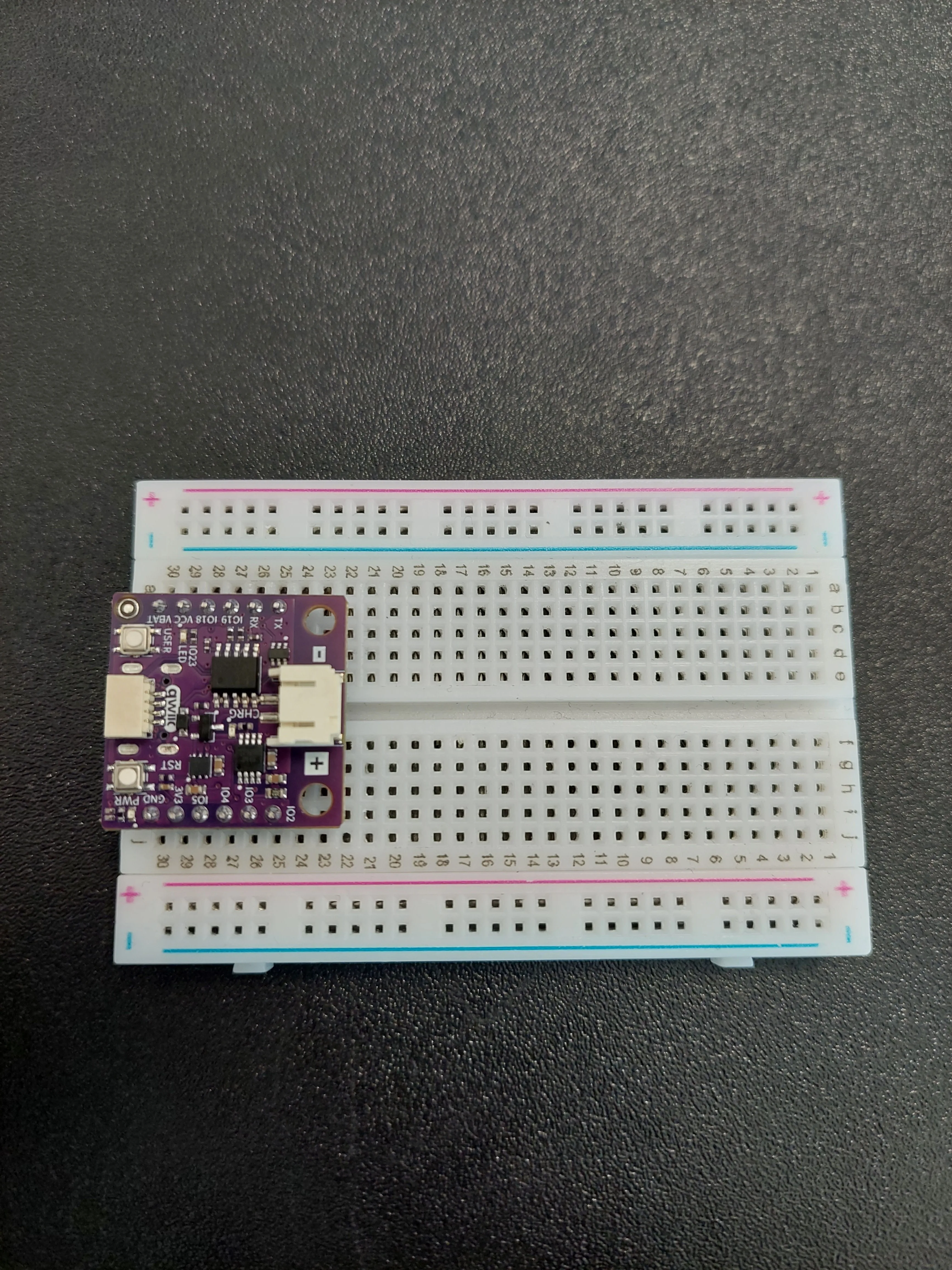
Both pins this project uses are on the f–j side of the board: IO2 in row 25 for the buzzer, and IO5 in row 28 for the LED. The board body covers columns f–i, so j25, j28 and j30 are the holes you can actually get a wire into. Everything else happens further along the same f–j side, well clear of the board.
IO5 on the f–j side and IO18 on the a–e side, and row 25 is IO2 on the f–j side but TX on the a–e side. Count the rows on the same side you are plugging into.1. Insert the NULA MINI board on the breadboard
Push the board into one end of the breadboard so that its two rows of pins sit on either side of the centre channel, with the chip facing down.
2. Place the buzzer and wire it to IO2
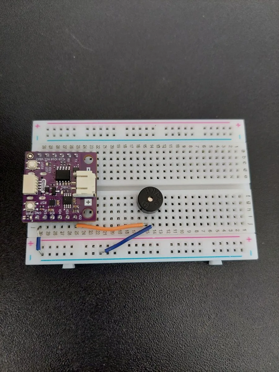
Three things happen in this step, because they belong together.
First run a jumper from j30 (GND) across to the blue − rail. That rail becomes the shared ground line for everything else in the project.
Then push the buzzer into the f–j side with its two legs in row 15 and row 14. Look at the top of its case before you do: next to the HWDZ moulding there is a small + inside a circle, and the leg on that side is the positive one. That leg goes into row 15.
Finally, one jumper from j15 to j25 (IO2) to carry the sound, and one from j14 to the blue − rail to complete the loop.
3. Run IO5 out to the LED and add the resistor
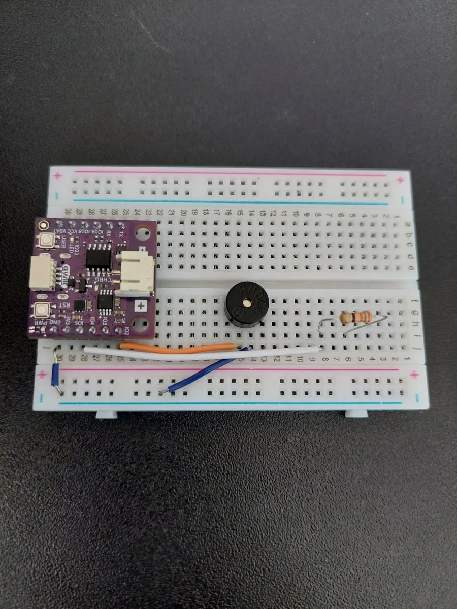
One jumper from j28 (IO5) along to j8. This is the wire that will switch the warning light.
Then the 330 Ω resistor from i8 to i6, bridging the two rows. Its bands read orange-orange-brown.
4. Add the LED
The LED goes in with its long leg in row 6, the row the resistor feeds, and its short leg in row 5.
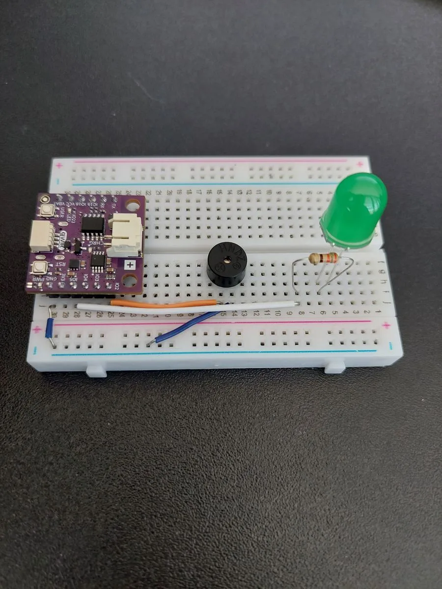
5. Connect the LED to ground
One last jumper, from j5 (the row holding the LED's short leg) across to the blue − rail.
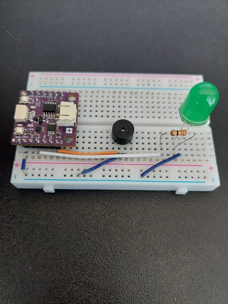
The chain is now closed end to end: IO5 → resistor → LED → GND.
6. Plug in the ultrasonic sensor
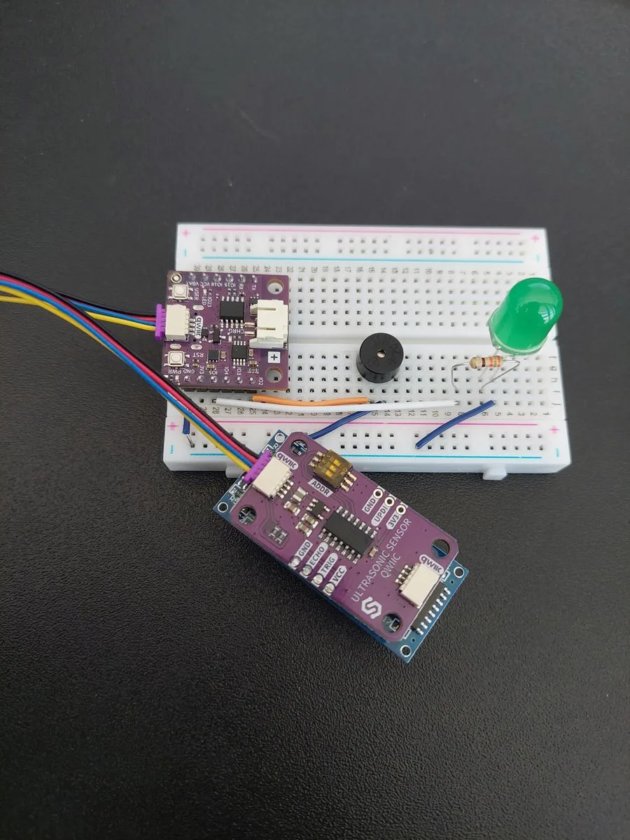
The sensor needs no breadboard holes at all. It is a Qwiic module, so one cable carries its power and its data together, and it only fits one way round.
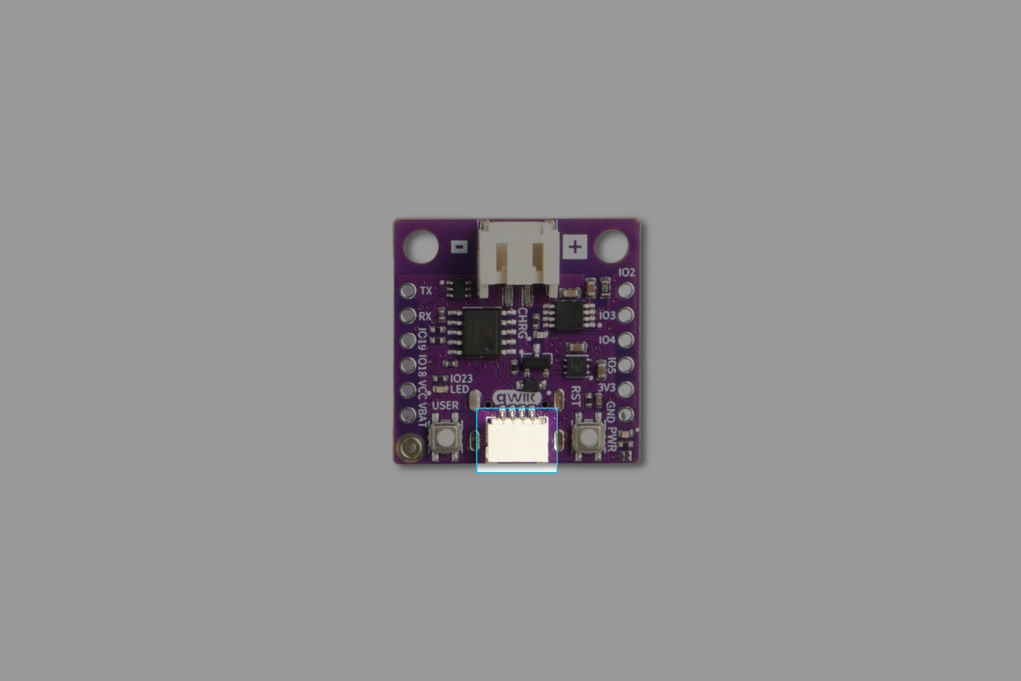
Plug one end into the board's Qwiic connector, the white one on the edge between the USER and RST buttons, and the other into either connector on the purple ULTRASONIC SENSOR QWIIC board. It has two, one at each end, wired together, so it makes no difference which you pick.
If you would like to see exactly which connector this is on a bare board, it is highlighted here:
ON marking. It sets the address the sensor answers to, and the code expects the factory setting.7. Connect the board to your computer
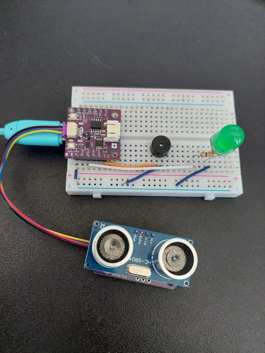
Turn the sensor so its two silver transducers face out into the room, keep the space in front of them clear, and plug in the USB-C cable.
How one number becomes five behaviours
Everything this project does comes from a single measurement, passed down a chain of if and else if:
| Distance | Buzzer | LED |
|---|---|---|
| more than 100 cm | silent | off |
| 60–100 cm | slow beeping, 800 ms apart | off |
| 30–60 cm | medium beeping, 400 ms apart | off |
| 10–30 cm | fast beeping, 150 ms apart | off |
| less than 10 cm | one continuous tone | on |
The board checks these ranges from the widest down and stops at the first one that matches, which is why each test only needs a lower bound. By the time it reaches else if (distance > 30), everything above 60 has already been dealt with.
Beeping without stopping the program
The obvious way to make a beep is tone(), delay(), noTone(), delay(). This sketch does not do that, and the reason is worth understanding, because it is one of the most useful ideas in the whole kit.
delay() does not mean "wait in the background". It means stop. During delay(800) the board does nothing else at all. It cannot measure, it cannot notice you moving closer, it cannot react. A parking sensor that stops looking for eight tenths of a second at a time is not much of a parking sensor.
So instead the sketch keeps a note of the time:
unsigned long lastBeep = 0;
unsigned long beepInterval = 0;
bool buzzerOn = false;
millis() returns how many milliseconds the board has been running. Every pass through the loop, the sketch subtracts the moment of the last change from the moment now, and only acts when enough time has gone by:
if (now - lastBeep >= beepInterval) {
  lastBeep = now;
  buzzerOn = !buzzerOn;
  if (buzzerOn) tone(BUZZER_PIN, TONE_FREQ);
  else          noTone(BUZZER_PIN);
}
The ! operator flips a true to false and back again, so each time the interval elapses the buzzer switches to the opposite of whatever it was. On, off, on, off: doing that over and over is what you hear as beeping. A smaller beepInterval means less waiting between switches, which is faster beeping.
Reading the sensor, and reading it correctly
Three details in the code deserve a closer look.
It takes two calls, not one
hc.takeMeasure();
delay(MEASURE_WAIT_MS);
uint16_t reading = hc.getDistance();
takeMeasure() only asks the sensor to go and do the work. The sensor then needs a moment (it gives up listening after about 38 milliseconds if no echo arrives), so the sketch waits 50 ms before getDistance() collects the finished answer. This is explained in full in 3.1 Measuring Distance.
That 50 ms wait is also the only pause in the whole loop, which is why there is no delay() at the bottom of it. The measurement sets the pace: about twenty readings every second.
The answer arrives in millimetres
int distance = reading / 10;
The sensor reports the distance in millimetres, so a reading of 250 means 25 centimetres. Every threshold further down the sketch is written in centimetres, because that is how a person would describe a distance, so the reading is converted once here and the converted value is what the if chain compares against.
distance > 100 would mean 10 cm rather than 1 m, and the whole parking sensor would end up working only inside a 10 cm bubble. Whenever you use a new sensor, check what unit it answers in before comparing it to anything.Zero is not a distance
if (reading == 0) {
  Serial.println("No echo received, nothing in range.");
  ...
  return;
}
The sensor answers 0 whenever it heard no echo it could use, and that happens in two opposite situations: when nothing is in range at all, and when something is closer than about 3 centimetres.
The second one surprises people. Every ultrasonic sensor has a blind zone right in front of it. The sensor sends out a burst of sound and then listens for it coming back, but from very close range the echo returns before the burst has finished, so it arrives while the sensor is still talking and is never heard.
Neither case is a real measurement. If the sketch treated 0 as a distance it would read as "zero centimetres away" and set off the alarm at full blast whenever the way was clear, so instead it falls silent and waits for the next reading.
Code
/**
 **************************************************
 *
 * @file        7.3_Parking_sensor.ino
 * @brief       Project that builds the parking sensor you know from cars. The Soldered Ultrasonic Distance Sensor
 *              watches for obstacles, and the closer one gets, the faster the buzzer beeps. Under 10 cm the beeping
 *              turns into one continuous tone and an LED lights up as a final warning.
 *              It builds on the distance measuring from section 3.1 and the buzzer from section 2.4.
 *              For details, connection diagram and more, check out the example documentation at: <link placeholder>
 * @author      Soldered
 ***************************************************
 */

/*
Include the Soldered library for the Ultrasonic Distance Sensor, so we can read the distance with a single function
call instead of timing the echo ourselves.
*/
#include "Ultrasonic-distance-sensor-easyC-SOLDERED.h"

/*
This is a variable to which we pass the number of pin that we had connected the buzzer to.
The NULA board has a pin naming logic as follows: IO2, where 2 is the number that we give to the variable.
*/
const int BUZZER_PIN = 2;

/*
This is a variable to which we pass the number of pin that we had connected the warning LED to.

Remember that the LED needs a 330 Ohm resistor in series with it. That resistor limits how much current flows, and
without it the LED draws more than either it or the pin is built for, so both can be damaged.
*/
const int LED_PIN = 5;

/*
Here we create our sensor object, which we named "hc". The sensor connects over easyC, which is Soldered's name for an
I2C connection over a single cable, so we pass no pin numbers: I2C always uses the same two pins on the board (IO6 and
IO7 on the NULA board) and the library already knows to look there.
*/
Ultrasonic_Sensor hc;

/*
This is how long we wait after asking for a measurement, in milliseconds. The sensor gives up listening for an echo
after 38 milliseconds, so waiting a little longer than that means the answer is always ready when we ask for it.
This wait also sets the pace of the whole loop, which is why there is no delay() at the bottom of it.
*/
const int MEASURE_WAIT_MS = 50;

/*
This is the frequency of the warning sound, in Hertz. A frequency is how many times per second the buzzer moves back
and forth, and our ears hear it as the pitch of the sound. Small buzzers like this one are loudest somewhere between
2 and 4 kHz, so feel free to experiment with this value until it sounds best to you.
*/
const int TONE_FREQ = 2700;

/*
These three variables are what lets us beep at different speeds without ever stopping the program.
"lastBeep" remembers the moment the buzzer was last switched on or off, "beepInterval" holds how long we want to wait
between those switches, and "buzzerOn" remembers whether the buzzer is currently sounding or silent.
*/
unsigned long lastBeep = 0;
unsigned long beepInterval = 0;
bool buzzerOn = false;

void setup()
{
  /*
  Serial.begin() establishes serial communication between your board and your computer via a USB cable. We use it here
  to watch the measured distance while we test the sensor.
  */
  Serial.begin(115200);

  /*
  begin() prepares the sensor for use. For an easyC sensor this starts the I2C communication and tells the library which
  address to talk to, which for this sensor is 0x30.
  */
  hc.begin();

  /*
  pinMode() is a function that configures the specified pin to behave either as an input or in this case as an output.
  Both the buzzer and the LED are things we write to, so both go into OUTPUT mode. Right after that we write LOW to the
  LED pin so the warning light starts out switched off.
  */
  pinMode(BUZZER_PIN, OUTPUT);
  pinMode(LED_PIN, OUTPUT);
  digitalWrite(LED_PIN, LOW);

  //Print out the initial message so we know that the program started successfully.
  Serial.println("Ultrasonic buzzer + LED reverse sensor started");
}

void loop()
{
  /*
  Reading an easyC sensor takes two steps. takeMeasure() asks the sensor to send out a pulse and time the echo, and the
  wait afterwards gives it the moment it needs to finish that work and store the answer.
  */
  hc.takeMeasure();
  delay(MEASURE_WAIT_MS);

  /*
  getDistance() then fetches the stored answer. Note the unit: the sensor reports the distance in MILLIMETERS, so a
  reading of 250 means the obstacle is 25 centimeters away. We keep it in a variable named "reading" so that the name
  reminds us it is not yet the unit we want to think in.
  */
  uint16_t reading = hc.getDistance();

  /*
  The sensor answers with 0 whenever it heard no echo it could use. That happens in two opposite situations: when
  nothing is in range at all, and when an object is closer than about 3 centimeters, because then the echo comes back
  before the sensor has finished sending and it never hears it. Neither is a real measurement, and treating one as a
  distance would set off the alarm whenever the way is clear, so instead we fall silent and wait for the next one.
  */
  if (reading == 0) {
    Serial.println("No echo received, nothing in range.");
    noTone(BUZZER_PIN);
    buzzerOn = false;
    digitalWrite(LED_PIN, LOW);
    return;
  }

  /*
  Now we turn the reading into centimeters, which is how we would naturally describe a distance to a person, and how
  every number further down this sketch is written. Ten millimeters make one centimeter, so we divide by ten. This is
  whole-number division, so 253 millimeters becomes 25 centimeters, and that is all the accuracy this sensor can
  honestly offer anyway.
  */
  int distance = reading / 10;

  //Print the measured distance to the Serial Monitor so we can follow along while testing.
  Serial.print("Distance from obstacle: ");
  Serial.print(distance);
  Serial.println(" cm");

  /*
  We switch the LED off at the start of every pass through the loop. Only the closest range switches it back on again
  a few lines below, so this one line saves us from having to turn it off in every other case.
  */
  digitalWrite(LED_PIN, LOW);

  /*
  This chain of if statements is the heart of the project: it turns a distance into a beeping speed. Each range gets a
  different value of beepInterval, and a smaller interval means less waiting between beeps, which we hear as faster
  beeping. The board checks the ranges from the widest down and stops at the first one that matches.
  Feel free to experiment with both the distances and the intervals.
  */
  if (distance > 100) {

    //Nothing in range. noTone() stops whatever sound the buzzer was making and an interval of 0 keeps it silent.
    beepInterval = 0;
    noTone(BUZZER_PIN);
  }
  else if (distance > 60) {

    //Between 60 and 100 cm, beep slowly.
    beepInterval = 800;
  }
  else if (distance > 30) {

    //Between 30 and 60 cm, beep at a medium speed.
    beepInterval = 400;
  }
  else if (distance > 10) {

    //Between 10 and 30 cm, beep quickly.
    beepInterval = 150;
  }
  else {

    /*
    Closer than 10 cm. Here we call tone() without an interval, which makes the buzzer sound continuously instead of
    beeping, and we light up the LED as a final warning.
    */
    tone(BUZZER_PIN, TONE_FREQ);
    beepInterval = 0;
    digitalWrite(LED_PIN, HIGH);
  }

  /*
  This is where the beeping itself happens. millis() is a function that returns the number of milliseconds passed
  since the board began running the current program. By comparing it against the moment of the last switch we can wait
  the right amount of time without using delay(), which would freeze the program and stop us from measuring.
  Every time the interval has passed we flip buzzerOn to its opposite value with the "!" operator, and then either
  start the tone or stop it. Doing that over and over is what produces a beep.
  */
  if (beepInterval > 0) {
    unsigned long now = millis();
    if (now - lastBeep >= beepInterval) {
      lastBeep = now;
      buzzerOn = !buzzerOn;
      if (buzzerOn) tone(BUZZER_PIN, TONE_FREQ);
      else          noTone(BUZZER_PIN);
    }
  }

}
What you should see
Open the Serial Monitor at 115200 baud. After the ROM boot messages, the sketch announces itself:
Ultrasonic buzzer + LED reverse sensor started
ESP-ROM:esp32c6-..., SPIWP, load: and entry are printed by the chip's built-in bootloader on every reset, before your program starts. They look alarming and mean nothing is wrong.From then on you get a line about twenty times a second. Move your hand slowly towards the sensor and watch the numbers come down:

That single run walks through the whole project. The readings start around 26 cm, which is fast beeping. They cross 10 cm about a third of the way down, and from there the beeping stops and holds one continuous tone while the warning light comes on.
12 cm to 25 cm and straight back to 10 cm. That stray reading is normal. An ultrasonic sensor sometimes catches an echo off your sleeve, the desk, or the edge of your hand instead of the flat of it. It does not matter here, because another measurement arrives 50 milliseconds later. This is worth remembering whenever you use a distance sensor: judge it on a run of readings, never on one.Inside 10 cm, the board looks like this:
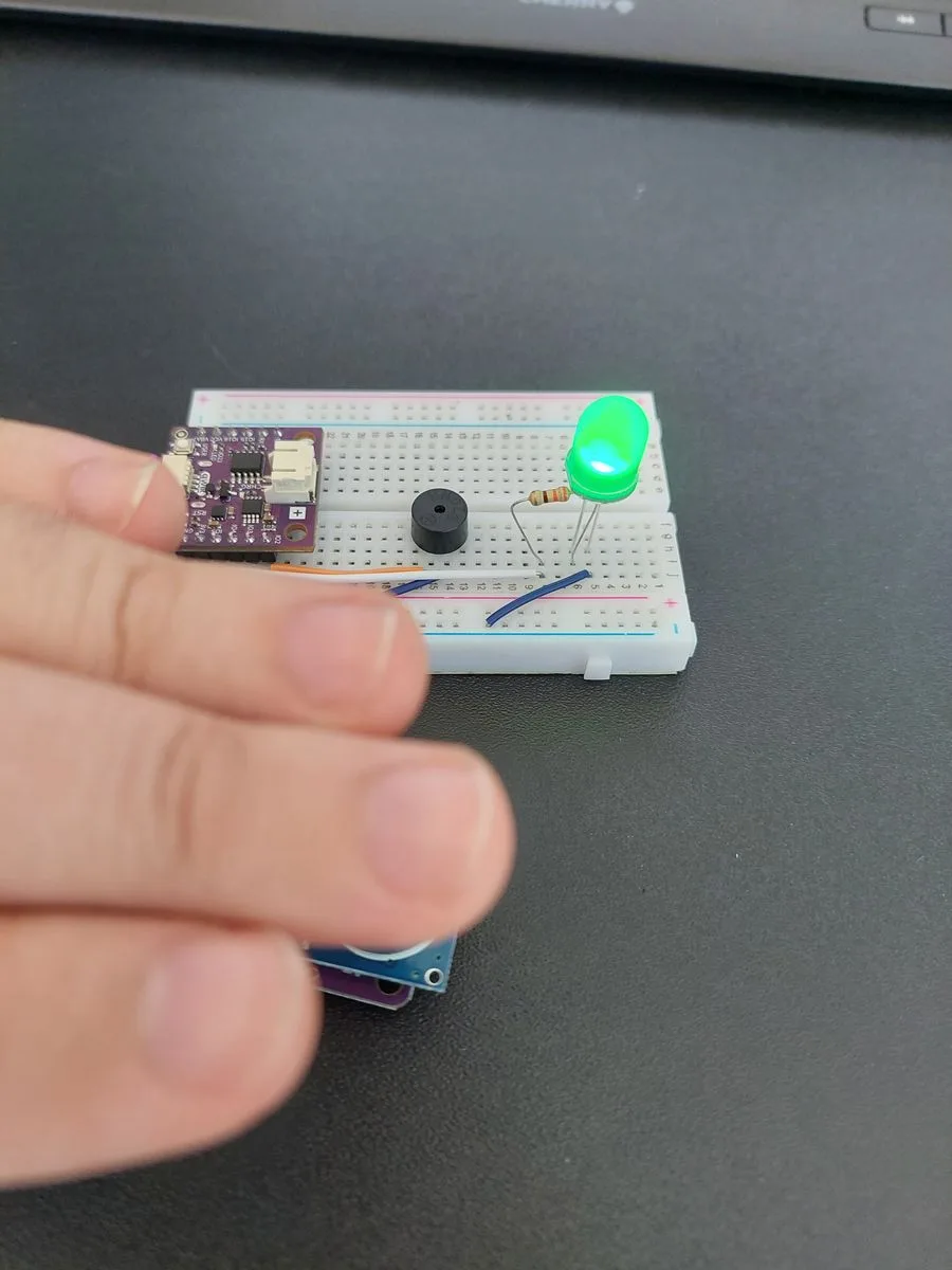
When nothing is in front of the sensor, or when something is pressed right up against it, you get this instead:
No echo received, nothing in range.
If the tone never goes solid, you are either not close enough, or you are too close. Remember the blind zone: an object touching the transducers makes the sensor stop answering, and everything falls silent. About 5 cm is the sweet spot.
If the tone goes solid but the LED stays dark, the code is doing its job and the fault is in the circuit. Check the LED is the right way round first: the long leg belongs in row 6, facing the resistor.
Full example
Check out the full example code on the link below:
7.3_Parking_sensor.ino
Project that uses an ultrasonic sensor, buzzer, and LED to simulate a reverse-parking warning system.