7.1 Smart Weather Station
This is the first project rather than an exercise, and the difference is that nothing in it is new. The sensor is the one from section 5, the display is the one from section 4, and the Wi-Fi is the one from section 6. What is new is that all three run at once, in one sketch, on one pair of wires: a board that measures the room, shows the reading on its own screen, and puts the same numbers on the internet where you can read them from anywhere.
That combination is what people mean by IoT: a small thing that senses something local and reports it somewhere else.
In this documentation you will learn:
- How to put two Qwiic modules on one bus, and why they do not interfere with each other.
- What an I2C address is for, in the one situation where it finally matters.
- How to send a measurement to a web server with an HTTP POST request.
- Why the display stays blank for the first thirty seconds, and why that is not a fault.
- Why the same reading is printed three different ways in the same sketch.
Hardware required:
- 1x Soldered NULA MINI board
- 1x Breadboard
- 1x Soldered SHTC3 temperature and humidity sensor
- 1x 16x2 LCD display with I2C adapter
- 2x Qwiic cables
- 1x USB-C cable
Putting the components together
Five steps, and three of them are just plugging a cable in.
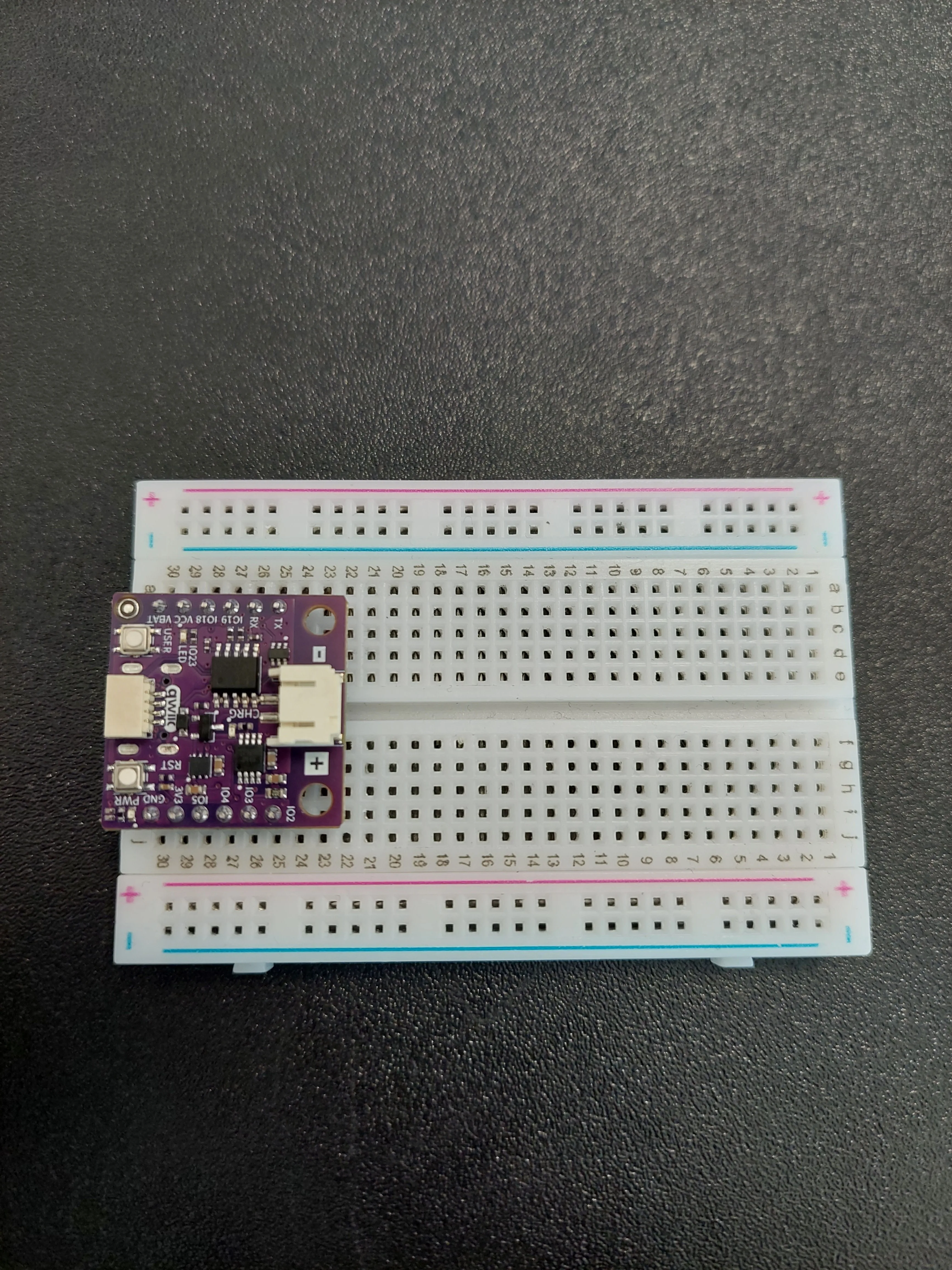
1. Insert the NULA MINI board on the breadboard
Push the board into one end of the breadboard so that its two rows of pins sit on either side of the centre channel. In the photos it occupies rows 25 to 30.
2. Plug the first Qwiic cable into the board
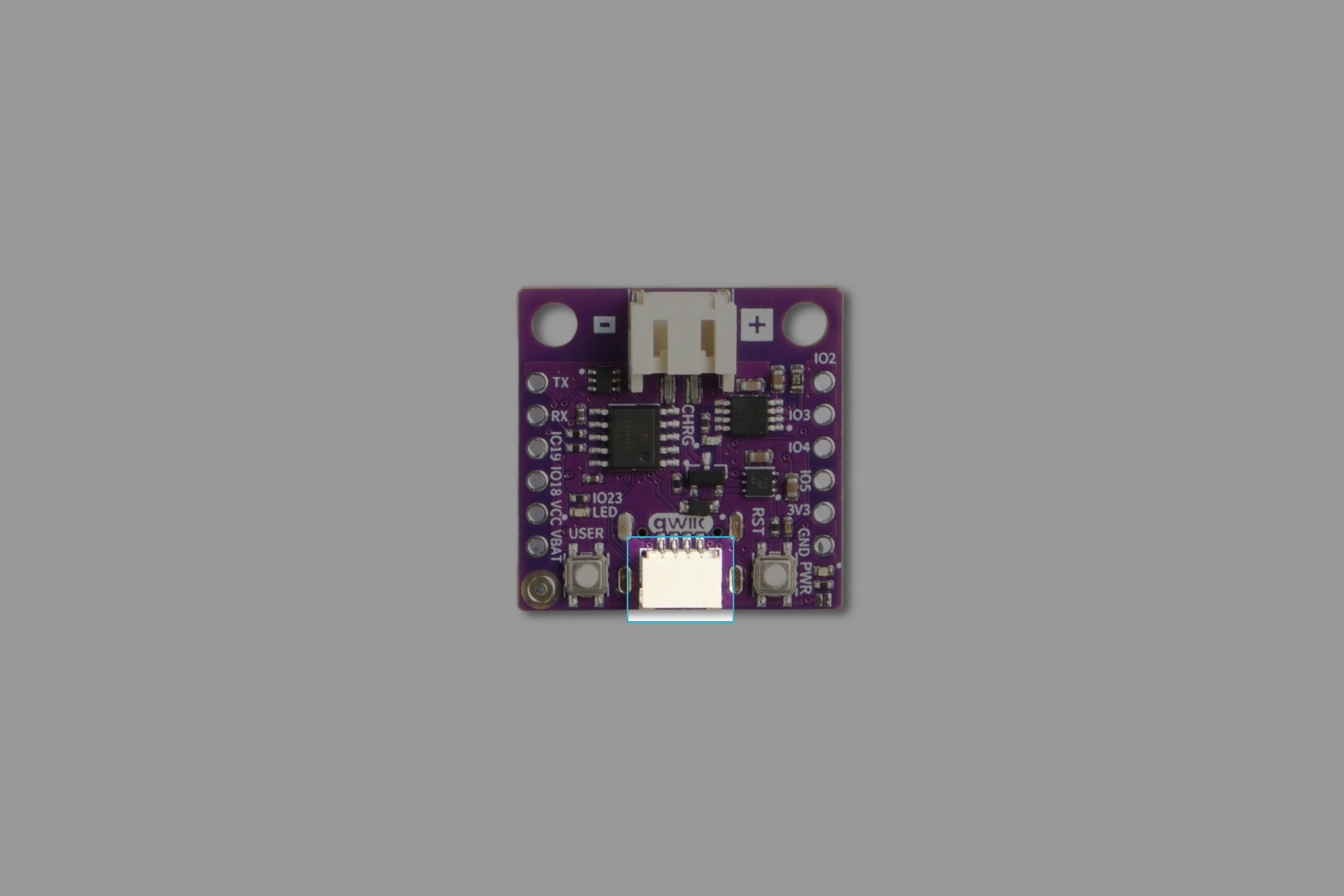
The NULA MINI has one Qwiic connector, on the edge of the board between the USER and RST buttons, marked qwiic on the silkscreen. Push the cable in until it clicks.
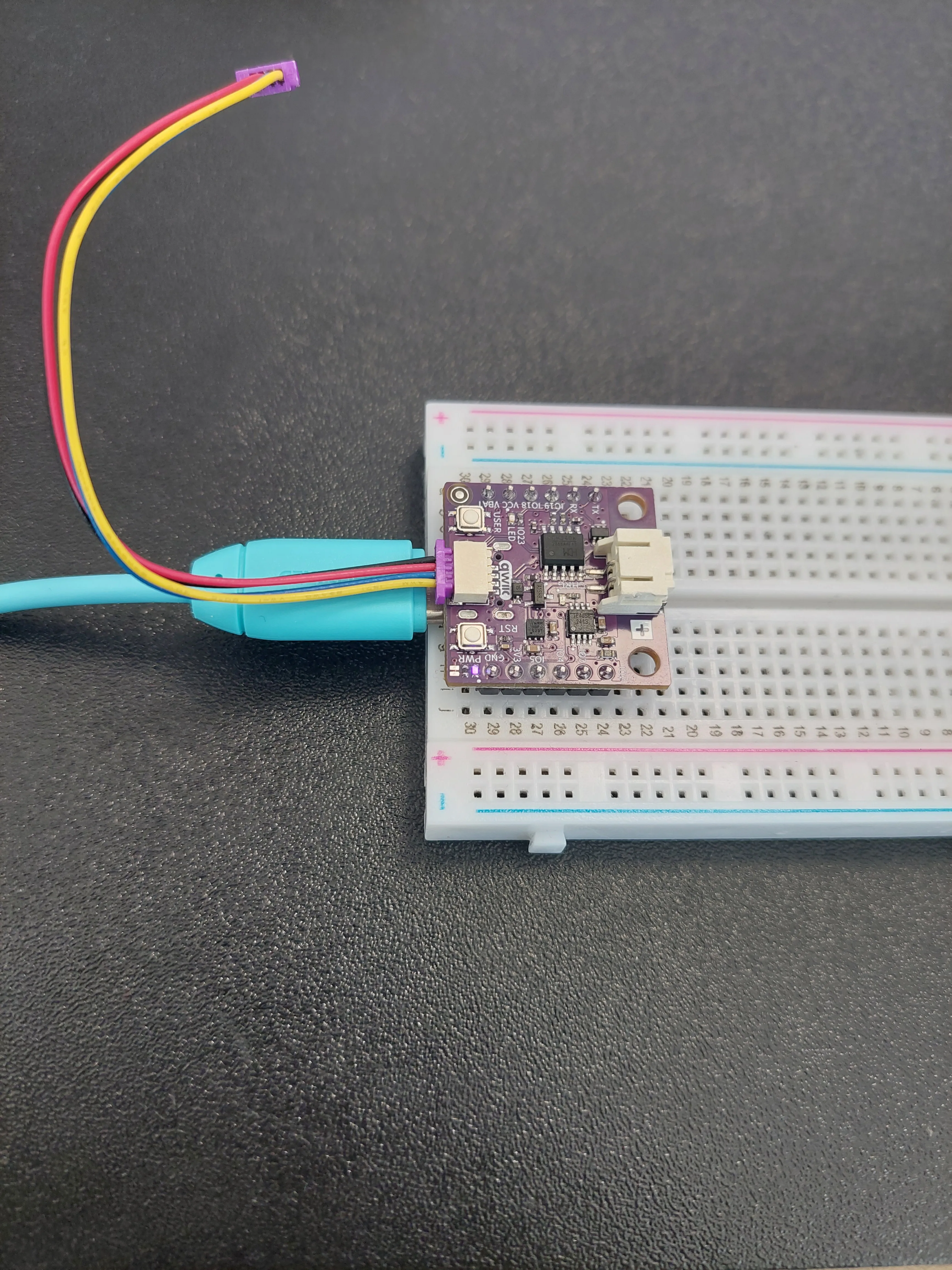
- and +. That one is the battery connector, and a Qwiic cable will not fit it.If you would like to see exactly which connector this is on a bare board, it is highlighted here:
3. Plug the other end into the SHTC3 sensor
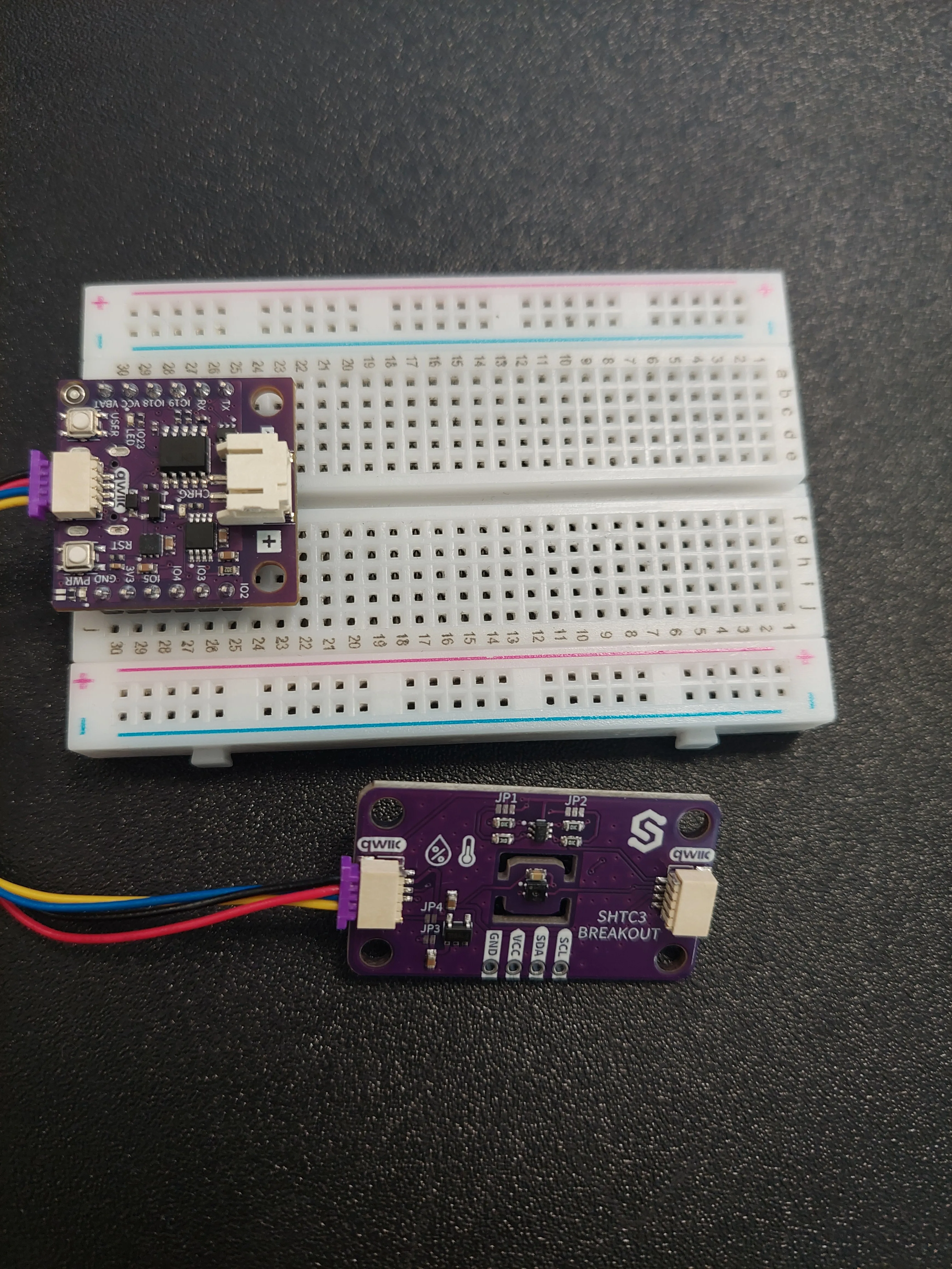
The sensor is the small purple board silkscreened SHTC3 BREAKOUT. It has two Qwiic connectors, one at each end. Plug the cable into either one, and leave the other free. This is the first time in the kit that the spare connector actually gets used.
4. Chain the display onto the sensor
Take the second Qwiic cable. Plug one end into the SHTC3's free connector, and the other into either of the two connectors on the purple I2C LCD ADAPTER on the back of the display.
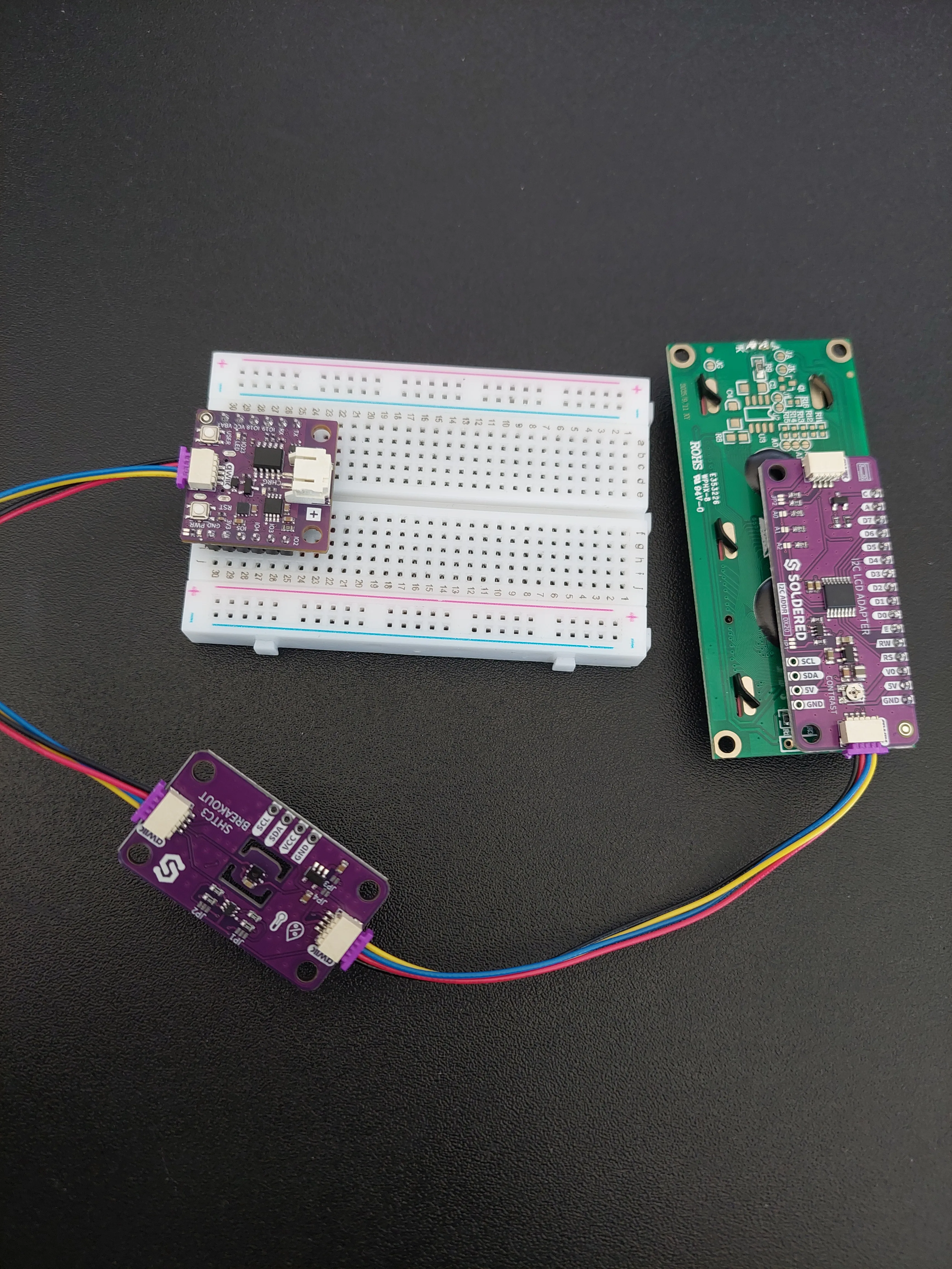
This is the only genuinely new connection in the project, and it is worth being clear about what it is not. The second cable does not run the display through the sensor, with the sensor passing data along. Both connectors on the SHTC3 are wired to the same four conductors: they are one junction with two sockets. Chaining simply saves you needing a board with three Qwiic connectors on it.
5. Connect the USB-C cable
Plug the USB-C cable into the board and into your computer. The purple PWR light comes on, and both modules are powered too. Everything on the chain takes what it needs through those same two cables.
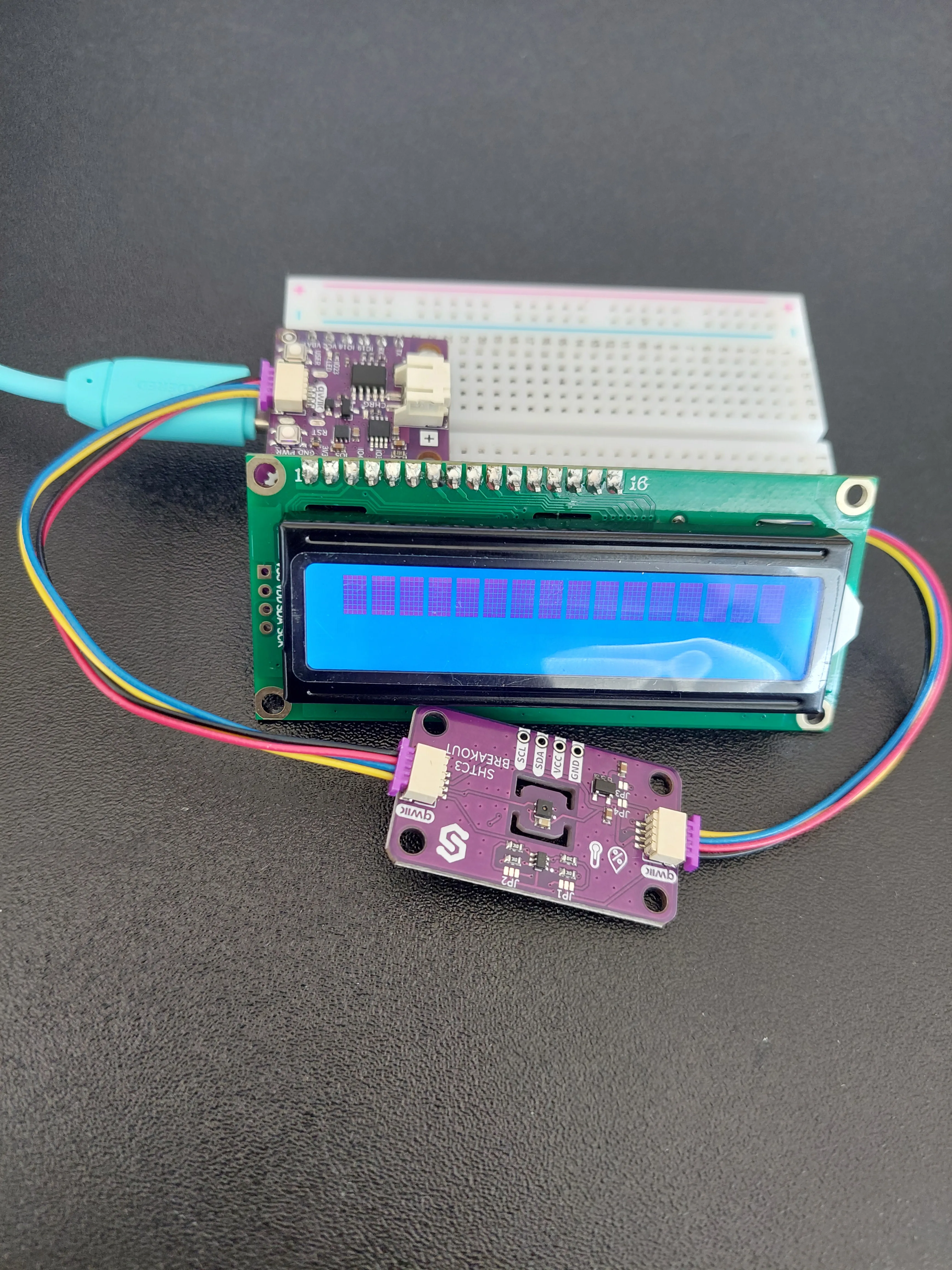
That row of solid blocks is worth a moment. It is what an HD44780 display shows when it has power but has never been initialized, the state it wakes up in before any sketch has spoken to it. You saw the other version of this in example 4.1, where the screen was lit but completely empty. Either appearance means the same thing: the display has power, and nothing beyond that can be concluded yet.
Two modules, one pair of wires
Every Qwiic example so far has used a single module, which meant the address printed on these boards never mattered. Here it does.
I2C is a bus. The two signal wires are shared by everything plugged into them, so when the board sends a byte, both the sensor and the display receive it. What stops the chaos is that every message begins with an address, and a module only reacts to messages carrying its own:
| Module | Address | Where it is written |
|---|---|---|
| 16x2 LCD, through its adapter | 0x20 | I2C ADDR 0X20, on the purple adapter |
| SHTC3 sensor | 0x70 | not printed, fixed inside the chip |
0x20 and 0x70 are different, so the two modules share one pair of wires and neither ever answers for the other. That is the whole trick, and it is why nothing in the sketch has to be told about the chaining. lcd.begin() and shtc3.begin() are written exactly as they were in 4.1 and 5.1.
A0, A1 and A2 pads on the LCD adapter are for: bridging them moves the display up to 0x27, so a second identical display could join the same cable. You will not need them here, since 0x20 and 0x70 were never going to collide.Setting up webhook.site
The sketch needs somewhere on the internet to send its readings, and webhook.site provides one for free with no account.
- Open webhook.site in a browser. It generates a unique URL for you the moment the page loads.
- Copy the address shown under Your unique URL. It looks like
https://webhook.site/fce7fced-1f3b-4ea1-8ed7-498130bbe714. - Leave that browser tab open. Every reading your board sends will appear in it.
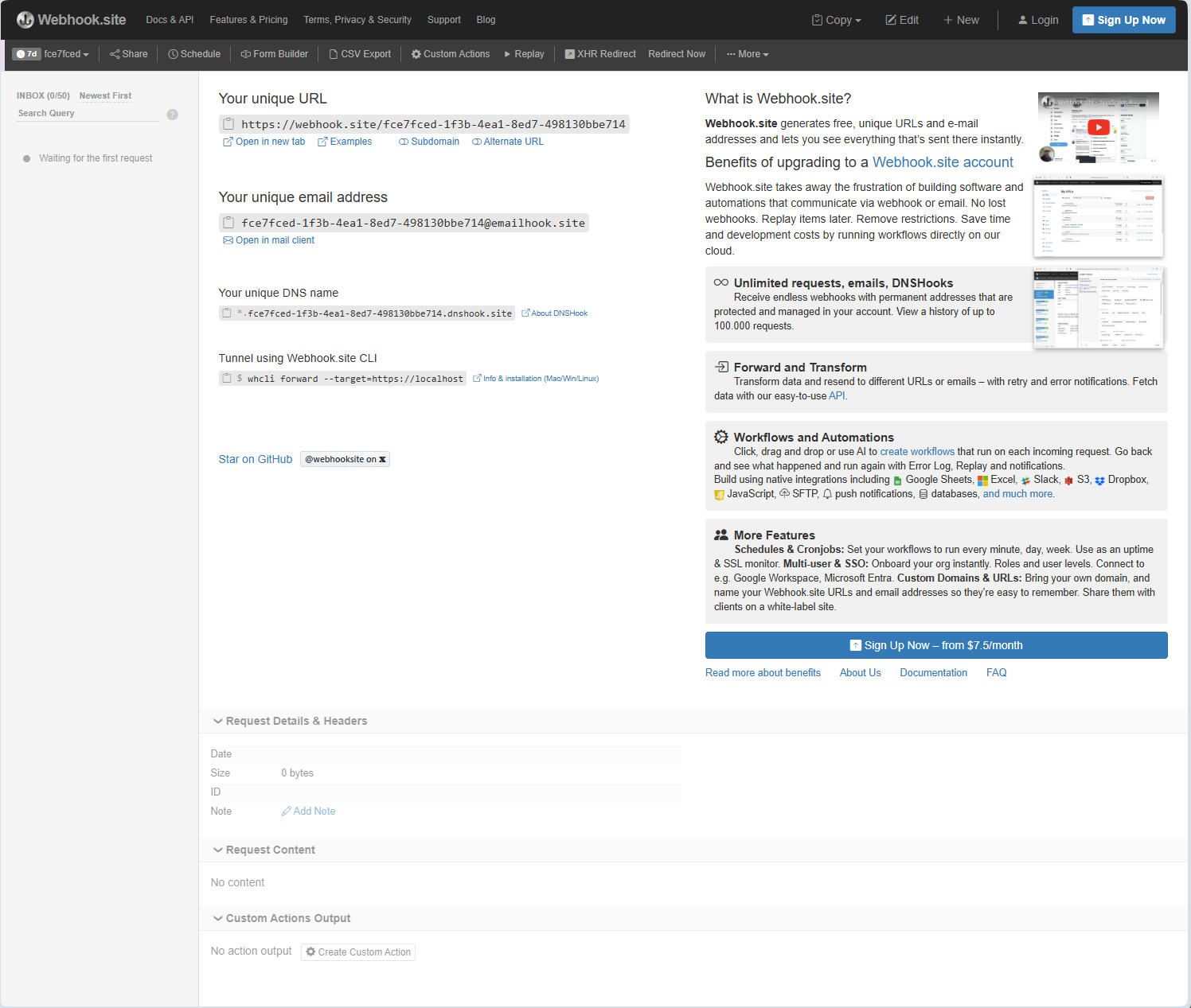
Then paste it into the sketch, replacing the placeholder text between the quotation marks:
const char* webhookURL = "https://webhook.site/your-unique-id";
While you are there, fill in your network details too:
const char* ssid = "your ssid";
const char* password = "your password";
7d badge beside the URL, and it holds 50 of them, which is the 0/50 counter. At one reading every thirty seconds, fifty requests is about 25 minutes before it quietly stops recording new ones.The first thirty seconds
There is one moment in this project that looks broken and is not, so it is worth knowing about before you upload rather than after.
Once setup() finishes, the sketch clears the display and drops into loop(). But a reading is only taken when millis(), the time since power-on, has moved UPDATE_MS past the last one, and lastUpdate starts at zero. So the first reading always lands thirty seconds after power-on, however quickly the rest of setup went.
In between, the display is lit and completely blank. It looks precisely like the contrast fault from example 4.1. It is not. Wait it out, and Temp: and Hum: appear together.
UPDATE_MS to something like 5000. Put it back before leaving the board running, though: at five seconds a reading, the free webhook page fills its fifty slots in about four minutes.The same reading, three ways
One measurement leaves the board by three different routes in this sketch, and each formats it differently. Seeing why is the quickest way to understand what is actually being sent.
Serial.print(temperature, 2);                                  // 27.93
lcd.print(temperature, 1);                                     // 27.9
String postData = "temperature=" + String(temperature, 2);     // temperature=27.93
The Serial Monitor gets two decimal places, because there is no shortage of room. The display gets one, because a 16-character row has to hold Temp: , the number, a degree symbol and a C. The POST gets two, because those numbers are going to a computer rather than to a person, and may as well arrive at full precision.
The degree symbol is the other difference:
Serial.print(" °C, Humidity: ");   // a real ° character
lcd.print((char)223);              // character number 223 in the display's own set
Your computer and the HD44780 do not use the same character set. Writing ° straight to the display would produce the wrong symbol, so the sketch asks for character 223 instead, which is where the degree sign lives in the display's built-in font.
print continues where the last one stopped. On the display they do not, because lcd.setCursor(0, 1) sends the cursor back to the start of the row every time, so you get a single dot that sits there and never moves.Code
/**
 **************************************************
 *
 * @file        7.1_Smart_Weather_Station.ino
 * @brief       Project that brings together three things you have already learned separately: the SHTC3 temperature
 *              and humidity sensor from section 5, the LCD display from section 4, and the Wi-Fi connection from
 *              section 6. The board measures temperature and humidity, shows them on the LCD, and sends them to a
 *              webhook on the internet so you can follow the readings from anywhere.
 *              For details, connection diagram and more, check out the example documentation at: <link placeholder>
 * @author      Soldered
 ***************************************************
 */

/*
The WiFi library contains everything needed to join a Wi-Fi network.
*/
#include <WiFi.h>

/*
The HTTPClient library lets us speak HTTP, so we can send our readings to a server.
*/
#include <HTTPClient.h>

/*
The Soldered library for the SHTC3 temperature and humidity sensor.
*/
#include "SHTC3-SOLDERED.h"

/*
The Soldered library for the LCD display.
*/
#include "LCD-SOLDERED.h"

/*
These two variables hold the name of your Wi-Fi network (the SSID) and its password. Replace the text between the
quotation marks with your own network details.
*/
const char* ssid = "your ssid";
const char* password = "your password";

/*
This variable holds the address we send our readings to. Open https://webhook.site in a browser, copy the unique link
it shows you, and paste it between the quotation marks below. Keep that browser tab open and you will see every
reading appear in it.
*/
const char* webhookURL = "your unique url";

/*
Here we create our two objects: one for the sensor and one for the display. An object is our way of talking to a
device: every function we call on it, we call through its name.
The sensor needs no pin numbers because it uses easyC, which is Soldered's name for an I2C connection over a single
cable, and I2C always uses the same two pins on the board (IO6 and IO7 on the NULA board).
*/
SHTC3 shtc3;
LCD lcd(16, 2);

/*
These two variables hold the latest readings. They are decimal numbers, which is why they are floats.
*/
float temperature = 0.0;
float humidity = 0.0;

/*
This variable remembers the moment of the last reading, and the one below it defines how much time passes between two
readings, in milliseconds. 30000 milliseconds is thirty seconds. Feel free to experiment with this value, but keep in
mind that every reading is also sent over the internet.
*/
unsigned long lastUpdate = 0;
const unsigned long UPDATE_MS = 30000;

void setup() {

  /*
  Serial.begin() establishes serial communication between your board and your computer via a USB cable. In a project
  this size the Serial Monitor is our main tool for finding out what went wrong, so we start it first.
  The short delay after it gives the connection a moment to settle, so the first messages are not lost.
  */
  Serial.begin(115200);
  delay(500);

  /*
  Here we prepare the display. begin() starts the communication with it, backlight() turns on its light so the text is
  readable, and clear() wipes anything that was left on the screen from before.
  setCursor() then chooses where the next text will appear: the first number is the column and the second is the row,
  and both start counting at zero. So (0, 0) is the top left corner and (0, 1) is the start of the second line.
  We show a short greeting first, so we can tell at a glance that the display itself works.
  */
  lcd.begin();
  lcd.backlight();
  lcd.clear();
  lcd.setCursor(0, 0);
  lcd.print("Weather Station");
  lcd.setCursor(0, 1);
  lcd.print("Starting...");
  delay(1000);
  lcd.clear();

  /*
  begin() on the sensor starts the I2C communication and tells us whether the sensor answered, returning true on
  success and false on failure. The "!" in front means "not", so this reads as "if the sensor did not start".
  If the sensor is missing there is nothing left for this project to measure, so instead of continuing we print the
  problem and stop here. The while(1) loop below never ends, which is a simple way of saying "go no further".
  */
  if (!shtc3.begin()) {
    Serial.println("SHTC3 init failed!");
    lcd.print("SHTC3 error!");
    while (1) delay(100);
  }

  /*
  WiFi.begin() starts the connection attempt. The function only starts the process, it does not wait for it to finish,
  so we tell the user what is going on both on the Serial Monitor and on the display.
  */
  Serial.print("Connecting to Wi-Fi");
  lcd.setCursor(0, 0);
  lcd.print("Connecting WiFi");
  WiFi.begin(ssid, password);

  /*
  Here we wait for the connection ourselves. WiFi.status() tells us the current state and WL_CONNECTED is the value it
  reports once we are online.
  */
  while (WiFi.status() != WL_CONNECTED) {
    delay(500);
    Serial.print(".");
    lcd.setCursor(0, 1);
    lcd.print(".");
  }

  /*
  WiFi.localIP() returns the address the router handed out to our board.
  */
  Serial.println();
  Serial.println("Wi-Fi connected!");
  Serial.print("IP: ");
  Serial.println(WiFi.localIP());

  //Let the user know we are online, then clear the display so the readings start on an empty screen.
  lcd.clear();
  lcd.print("WiFi Connected!");
  delay(800);
  lcd.clear();

  Serial.println("Smart Weather Station ready!");
}

void loop() {

  /*
  millis() is a function that returns the number of milliseconds passed since the board began running the current
  program. We use it instead of delay() so the board stays free to do other work between readings.
  */
  unsigned long now = millis();

  /*
  Here we check how much time has passed since the last reading. Only when UPDATE_MS milliseconds have gone by do we
  take a new one, and we immediately remember the current time as the new starting point.
  */
  if (now - lastUpdate >= UPDATE_MS) {
    lastUpdate = now;

    /*
    sample() tells the sensor to perform a fresh measurement, and the two read functions then hand us the results.
    We have to call sample() first, otherwise we would keep getting the previous measurement.
    */
    shtc3.sample();
    temperature = shtc3.readTempC();
    humidity = shtc3.readHumidity();

    //Print the readings to the Serial Monitor. The number 2 tells the function how many decimal places to show.
    Serial.print("Temperature: ");
    Serial.print(temperature, 2);
    Serial.print(" °C, Humidity: ");
    Serial.print(humidity, 2);
    Serial.println(" %");

    /*
    Now we show the same readings on the display. We clear it first, because writing shorter text over longer text
    would leave leftover characters behind.
    The (char)223 is the character code the display uses for the degree symbol. The Serial Monitor and the LCD do not
    use the same character set, which is why we write the degree sign one way above and another way here.
    */
    lcd.clear();
    lcd.setCursor(0, 0);
    lcd.print("Temp: ");
    lcd.print(temperature, 1);
    lcd.print((char)223);
    lcd.print("C");

    lcd.setCursor(0, 1);
    lcd.print("Hum: ");
    lcd.print(humidity, 1);
    lcd.print(" %");

    /*
    Before sending anything we check that we are still online. A Wi-Fi connection can drop at any time, and trying to
    send data without one would only waste time and print errors.
    */
    if (WiFi.status() == WL_CONNECTED) {

      /*
      Here we create our HTTP client object, prepare the request with begin(), and describe the format of our data
      with addHeader(). A header tells the server something about the request itself.
      */
      HTTPClient http;
      http.begin(webhookURL);
      http.addHeader("Content-Type", "application/x-www-form-urlencoded");

      /*
      Here we build the data we are going to send. The format "name=value&name=value" is the same one a browser uses
      when you submit a simple web form: the ampersand ("&") separates one value from the next, and String() converts
      our numbers into text so they can be joined to the rest with a plus sign.
      */
      String postData = "temperature=" + String(temperature, 2) + "&humidity=" + String(humidity, 2);

      /*
      POST() sends the request together with our data and waits for the answer. It returns a response code: numbers of
      200 and above mean the server answered, while a negative number means we never got an answer at all.
      */
      int httpCode = http.POST(postData);

      if (httpCode > 0) {
        Serial.print("POST successful! Response code: ");
        Serial.println(httpCode);
      } else {

        //errorToString() turns the negative error code into a short sentence that is easier to understand.
        Serial.print("POST failed. Error: ");
        Serial.println(http.errorToString(httpCode));
      }

      /*
      end() closes the connection and frees the memory the client was using. Always close a connection once you are
      done with it, otherwise a program that makes many requests will slowly run out of memory.
      */
      http.end();
    } else {

      //If we lost the connection, start a new attempt and try again on the next reading.
      Serial.println("Wi-Fi disconnected. Trying to reconnect...");
      WiFi.begin(ssid, password);
    }
  }
}
What you should see
Upload the sketch, then open the Serial Monitor and set it to 115200 baud. Keep your webhook.site tab open beside it. There are three places to watch, and they should agree with each other.
On the display
After the Weather Station / Starting... greeting, the Connecting WiFi message, and the thirty-second wait, the readings appear:
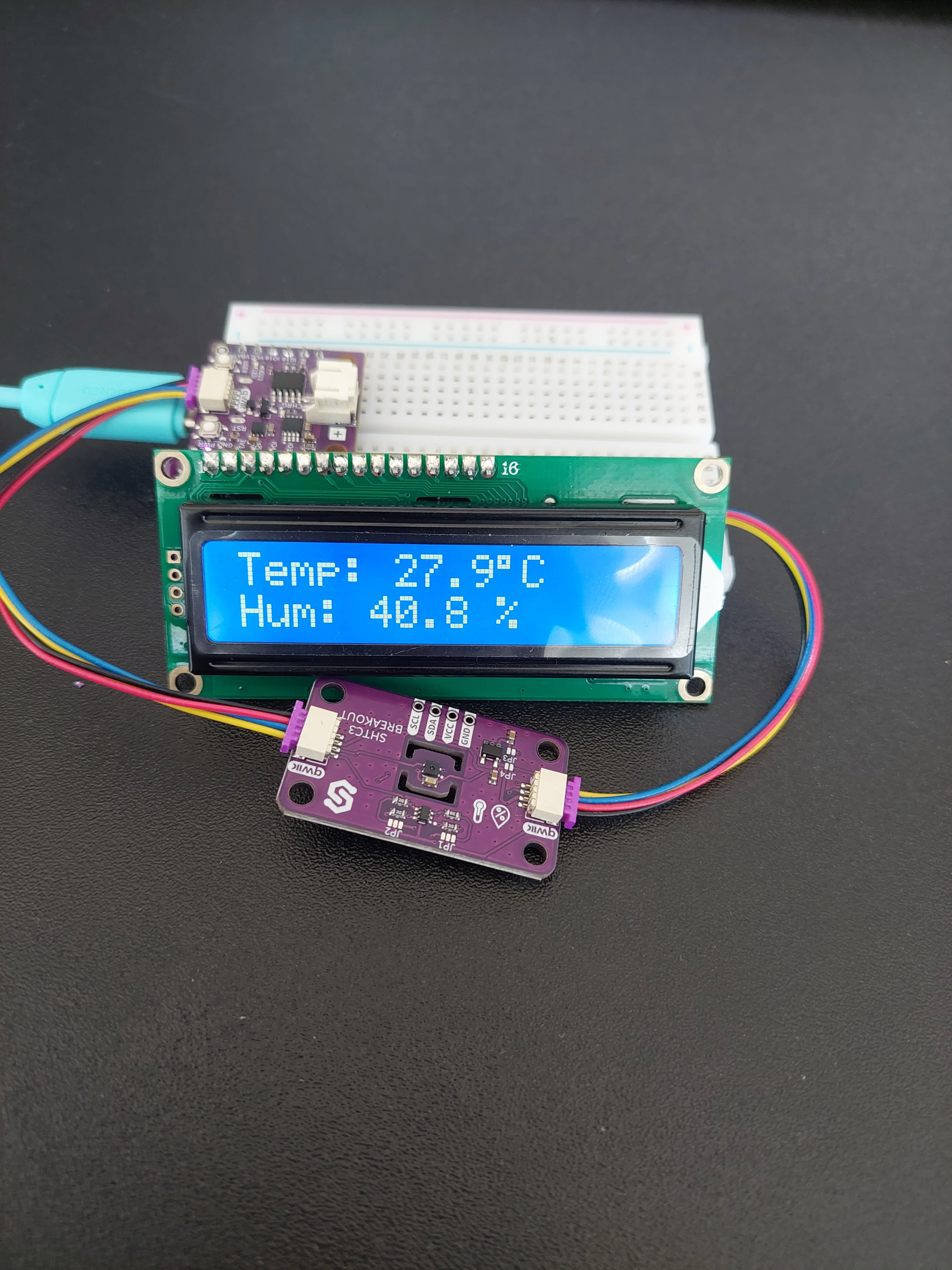
Breathe gently on the sensor from a few centimetres away and the humidity figure climbs within a second or two, but you will only see it on the next reading, up to thirty seconds later. That delay is the clearest reminder that the display is not connected to the sensor in any live sense: it is showing whatever the last trip round loop() put there.
On the Serial Monitor

Reading down from the blank line:
Connecting to Wi-Fi............shows twelve dots, one every 500 ms, so this board took about six seconds to join the network. The row of dots is a usable stopwatch.IP: 192.168.75.75is the address your router handed the board. It is a private address, only meaningful inside your own network.Smart Weather Station ready!is the last line ofsetup(). Everything after this comes fromloop().Temperature: 27.93 °C, Humidity: 40.80 %is the reading, at two decimal places. Compare it with the display photo above:27.93shown as27.9,40.80shown as40.8. Same measurement, two formats.- In
POST successful! Response code: 200, the200is the HTTP code for "fine, I have it".
On webhook.site
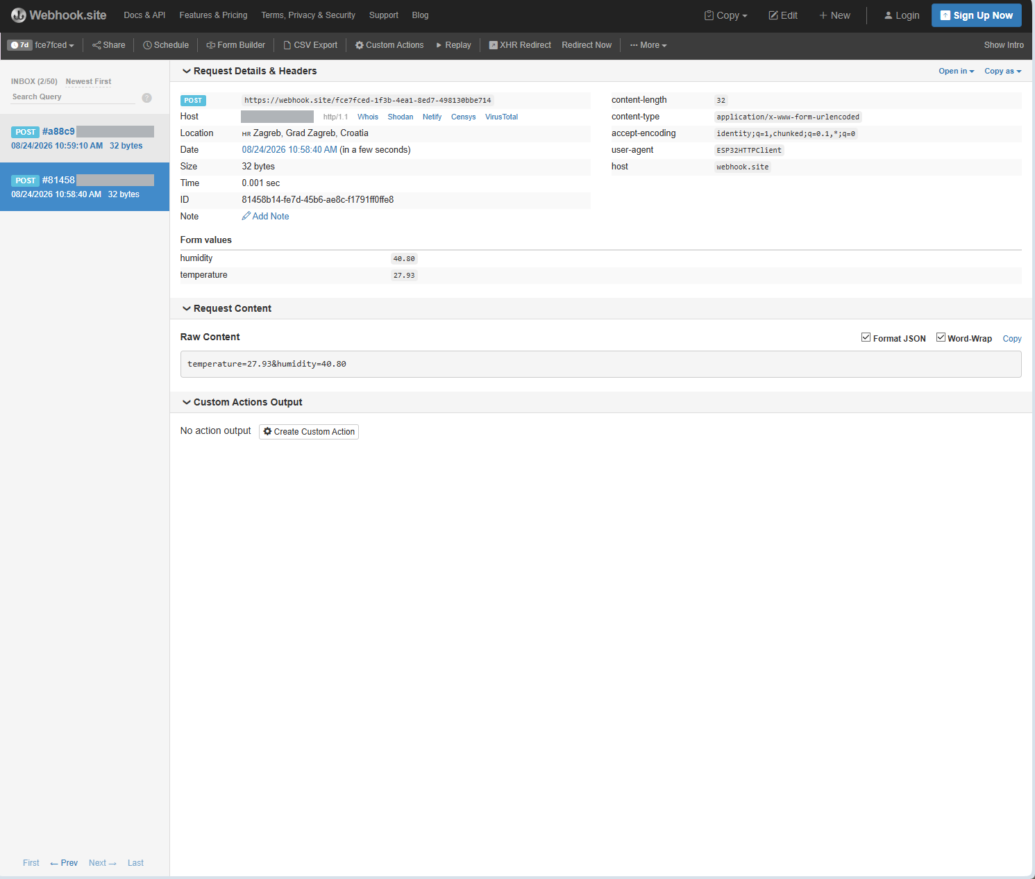
This page has more to say than the Serial Monitor does:
- The timestamps are
10:58:40and10:59:10: exactly thirty seconds apart. That is far better proof thatUPDATE_MSis doing its job than anything printed on the board itself. Form valuesliststemperatureandhumidityas separate named fields. They are only broken out like that because ofhttp.addHeader("Content-Type", "application/x-www-form-urlencoded"). Without that header the server would receive the same characters and have no idea they were meant as a form.Raw Contentshows what was actually sent:temperature=27.93&humidity=40.80. That is exactly the stringpostDatawas built from, and it matches the Serial Monitor line character for character.Size: 32 bytesis that string's length. Count it if you like: the&and the=signs are part of the payload too.user-agent: ESP32HTTPClientis howHTTPClientintroduces itself. Your board announced what it was without being asked.
Host field is greyed out in this screenshot on purpose. It shows the public address of the router the board sits behind, not the 192.168.75.75 the board printed. Both are correct: your router replaces the private address with its own public one on the way out, a process called NAT, and the server on the far side can only ever see the router. Webhook.site puts Whois and Shodan links beside it, which is a fair reminder that a public IP is worth being careful with.SHTC3 init failed! on the display and in the Serial Monitor, the sketch stops there deliberately and never reaches the Wi-Fi part. Check the Qwiic cables are pushed fully home at all four ends, then check that Soldered NULA Mini ESP32C6 is the selected board. Picking any other board sends the I2C traffic to the wrong pins, and it still compiles and uploads perfectly.CONTRAST silkscreen. Turn it slowly with a screwdriver until the characters appear. See 4.1 Print Message for the full description of this fault, but remember to rule out the thirty-second wait first.Where to take it next
Everything in this project is one variable away from being something else:
- Change
UPDATE_MSand you change how often the room is sampled. - Swap the two
lcd.printlines and the display shows humidity first. - Add a third name and value to
postDataand the webhook page grows a third form field.
The one thing you cannot do from here is read the data back: webhook.site shows you requests as they arrive, but it is not a place to keep them. Sending the same POST to a spreadsheet service or a database instead is the natural next step, and nothing about the board or the wiring would have to change.
Full example
Check out the full example code on the link below:
7.1_Smart_Weather_Station.ino
Project that measures temperature and humidity with the SHTC3 sensor, displays the readings on a 16x2 LCD, and sends them to webhook.site every 30 seconds.