3.2 Distance Fade LED
In 3.1 Measuring Distance the sensor's reading went straight to the Serial Monitor and nowhere else. This example takes the same reading and does something with it: the closer an object is to the sensor, the brighter an LED glows.
That is a bigger step than it sounds. Until now a pin has been either on or off, and an LED either lit or dark. Here the pin has to produce everything in between, and the distance in centimetres has to be turned into a brightness level. Two new functions do that work: analogWrite() and map().
In this documentation you will learn:
- What PWM is, and how it makes a digital pin behave like a dimmer.
- How to use
analogWrite()to set a brightness instead of just HIGH or LOW. - Why
analogWriteResolution()has to be set first, or the LED will not dim at all. - How clamping keeps a measurement inside a range the rest of the code can trust.
- How
map()rescales one range into another, and what happens when you reverse it.
Hardware required:
- 1x Soldered NULA MINI board
- 1x Breadboard
- 1x Ultrasonic distance sensor (HC-SR04)
- 1x Qwiic cable
- 1x LED (any colour)
- 1x 330 Ω resistor
- 3x Jumper wires
- 1x USB-C cable
Putting the components together
1. Insert the NULA MINI board on the breadboard
Push the board into one end of the breadboard so that its two rows of pins sit on either side of the centre channel, with the chip facing down. It will occupy rows 25 to 30.
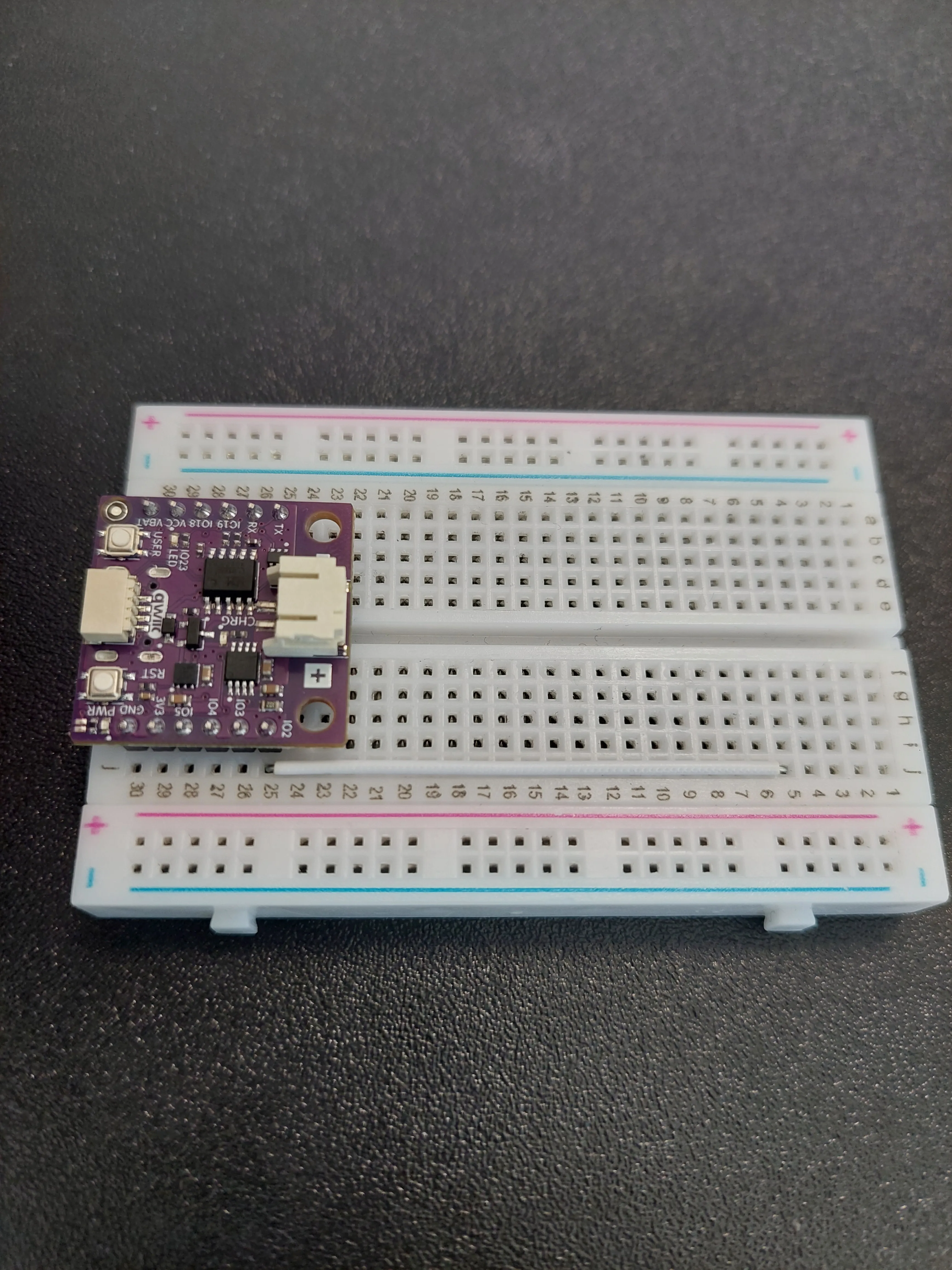
2. Bring IO2 out to a free row
IO2 is the pin that will drive the LED, and the board covers all of row 25 except the outermost hole. So the first wire simply carries that pin somewhere you can work: a jumper from j25 up to j15.
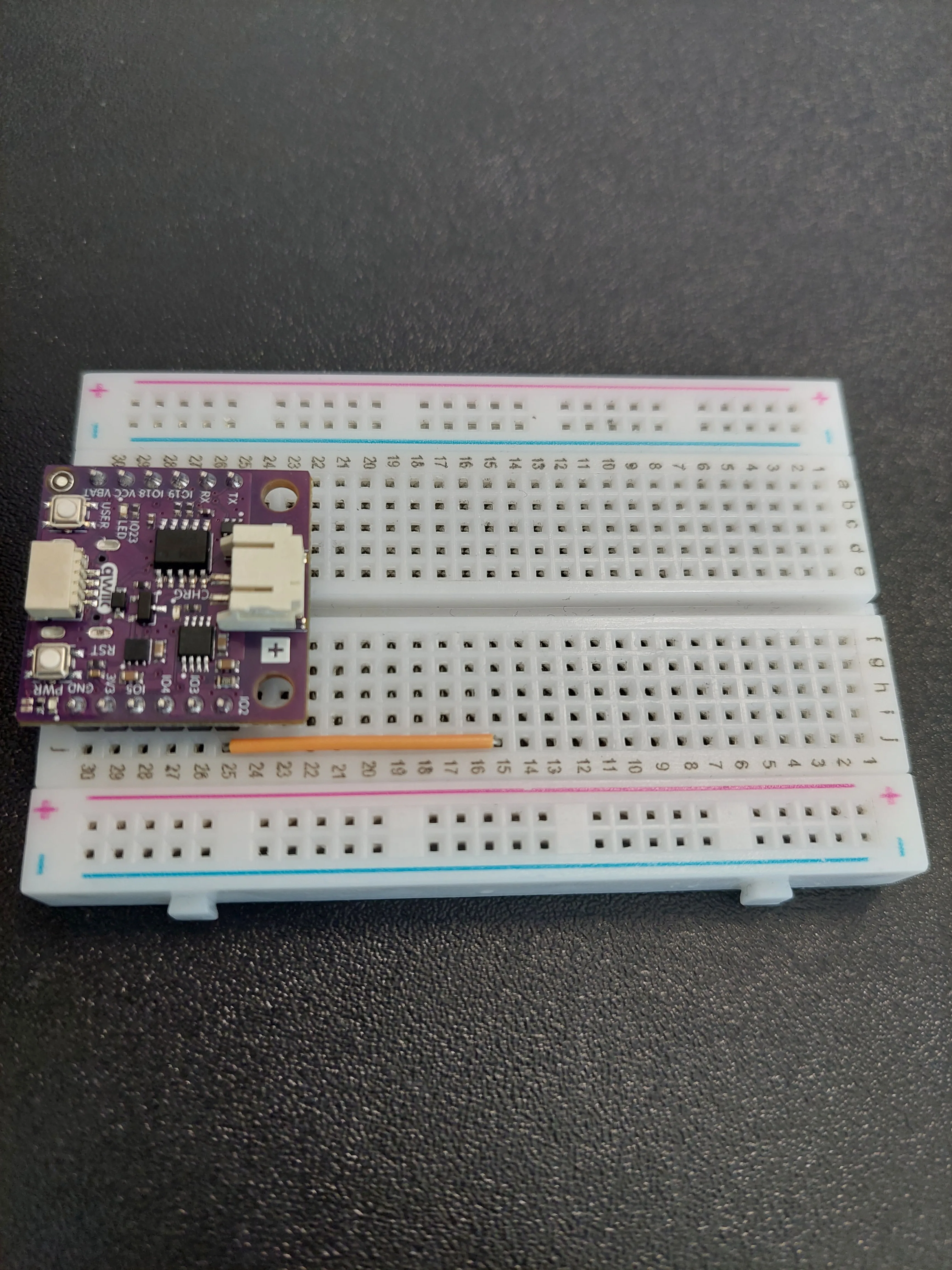
3. Add the 330 Ω resistor
The resistor is the next link in the chain. Place it so it bridges row 15, the row the jumper just arrived in, and row 13, both on the f–j side.
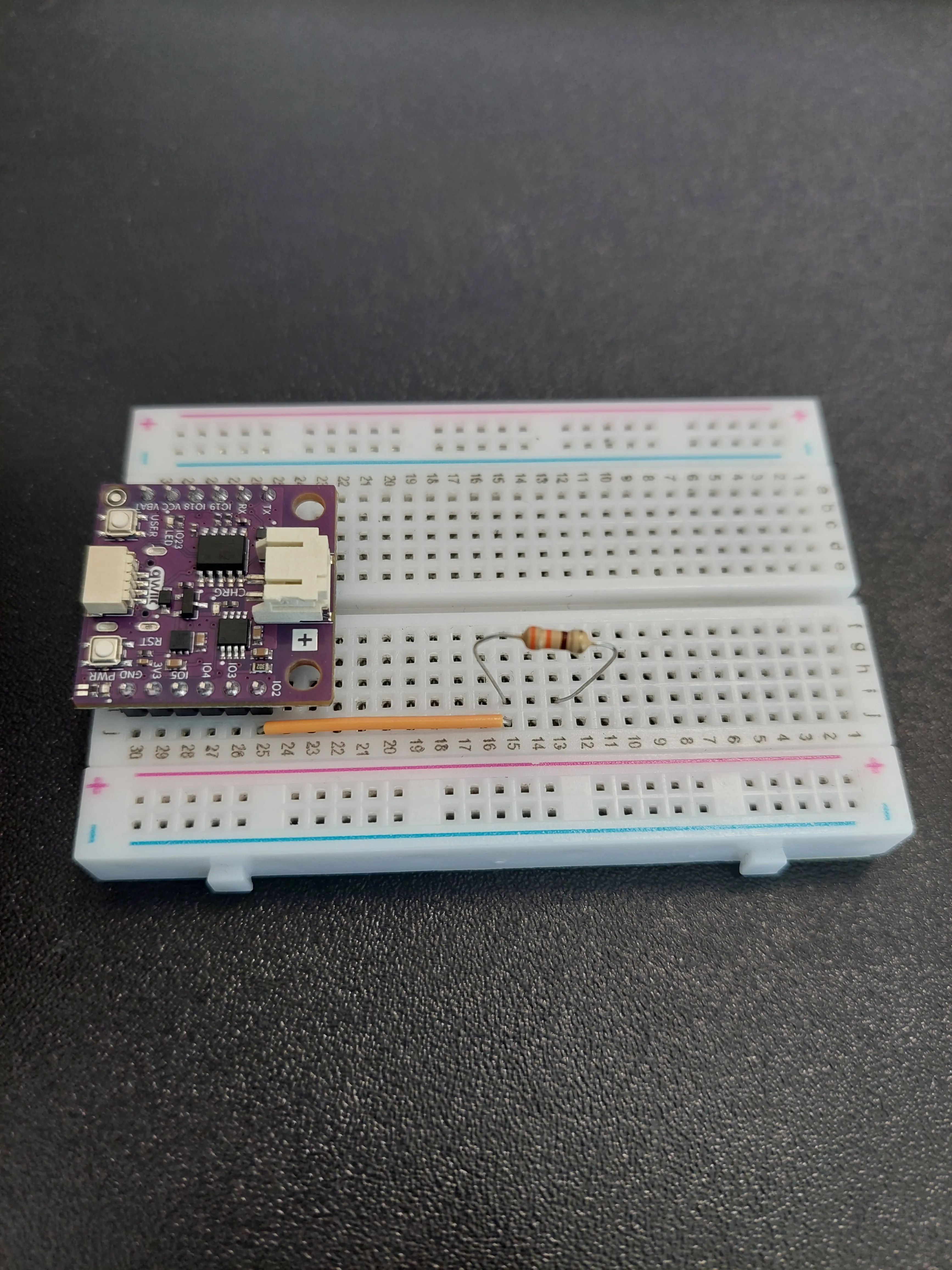
4. Add the LED
The LED continues the chain: its long leg (anode) into row 13, the same row the resistor ends in, and its short leg (cathode) into row 11.
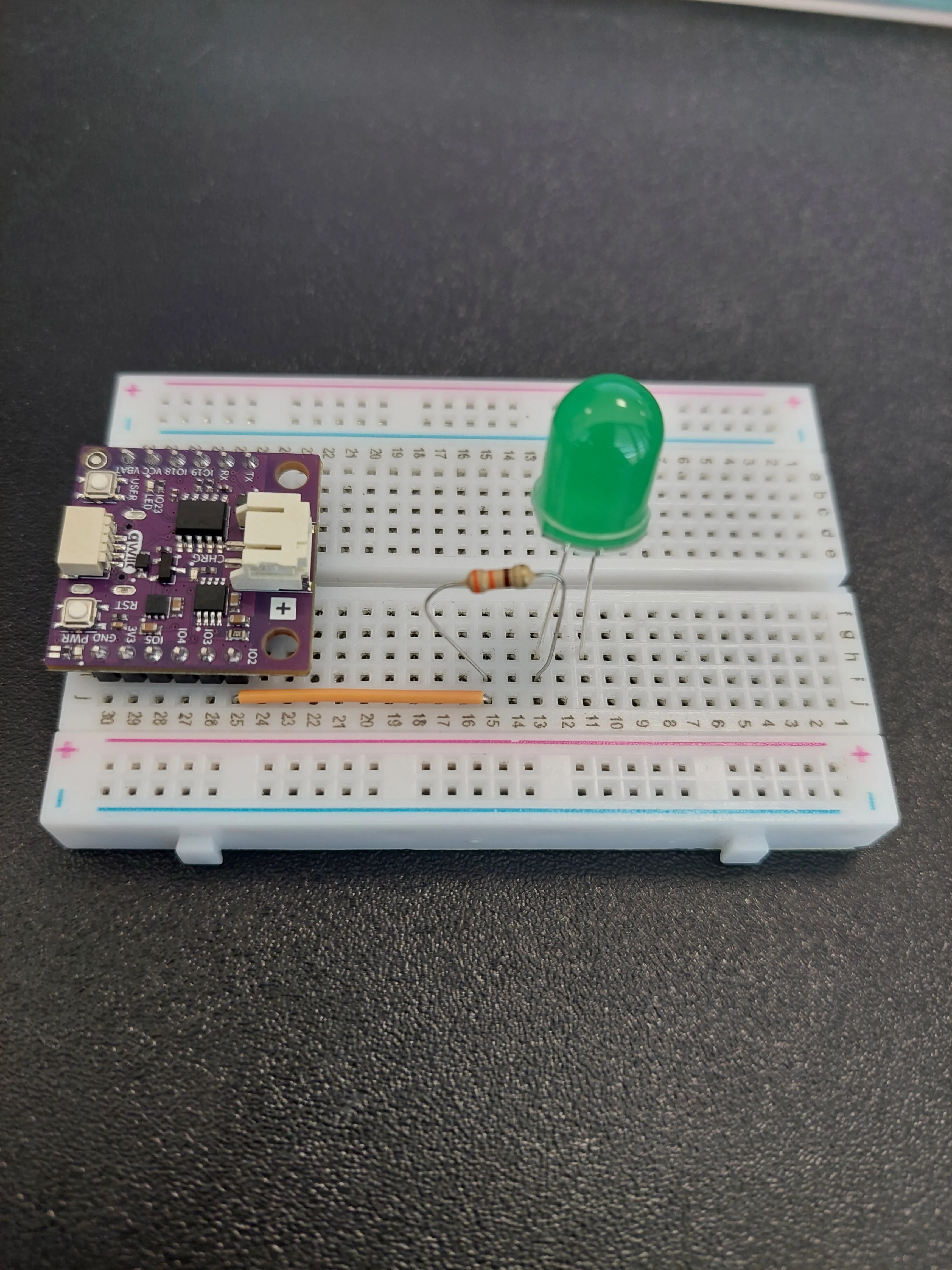
5. Ground the LED and the board
Two jumpers finish the circuit, and both go to the blue − rail, which acts as a shared ground line:
- From row 11, where the LED's short leg sits, across to the blue − rail.
- From j30 (
GND) across to that same rail.
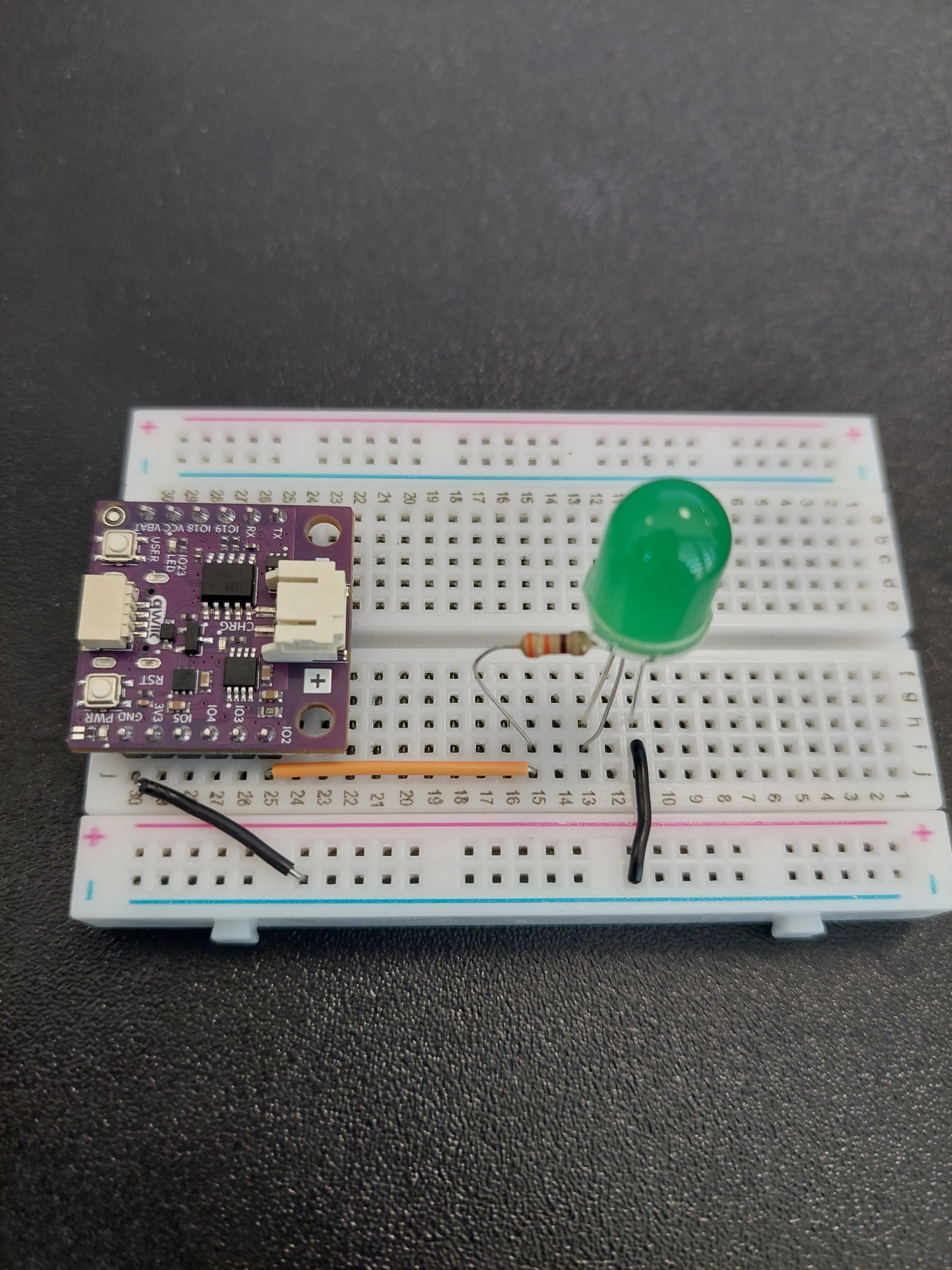
The full path is now IO2 → 330 Ω → LED → − rail → GND. This is the same chain as 1.2 LED Blink, built on a different pin. The difference is entirely in the code: instead of switching the pin on and off, we will hold it somewhere in between.
IO2, then the resistor, then the LED, then ground.6. Plug in the sensor and the USB-C cable
The sensor needs no wiring at all. It is a Qwiic module, so one cable from the board's qwiic connector, the white one between the USER and RST buttons, to either connector on the sensor carries power and data together. If you have just come from 3.1 it is already plugged in.
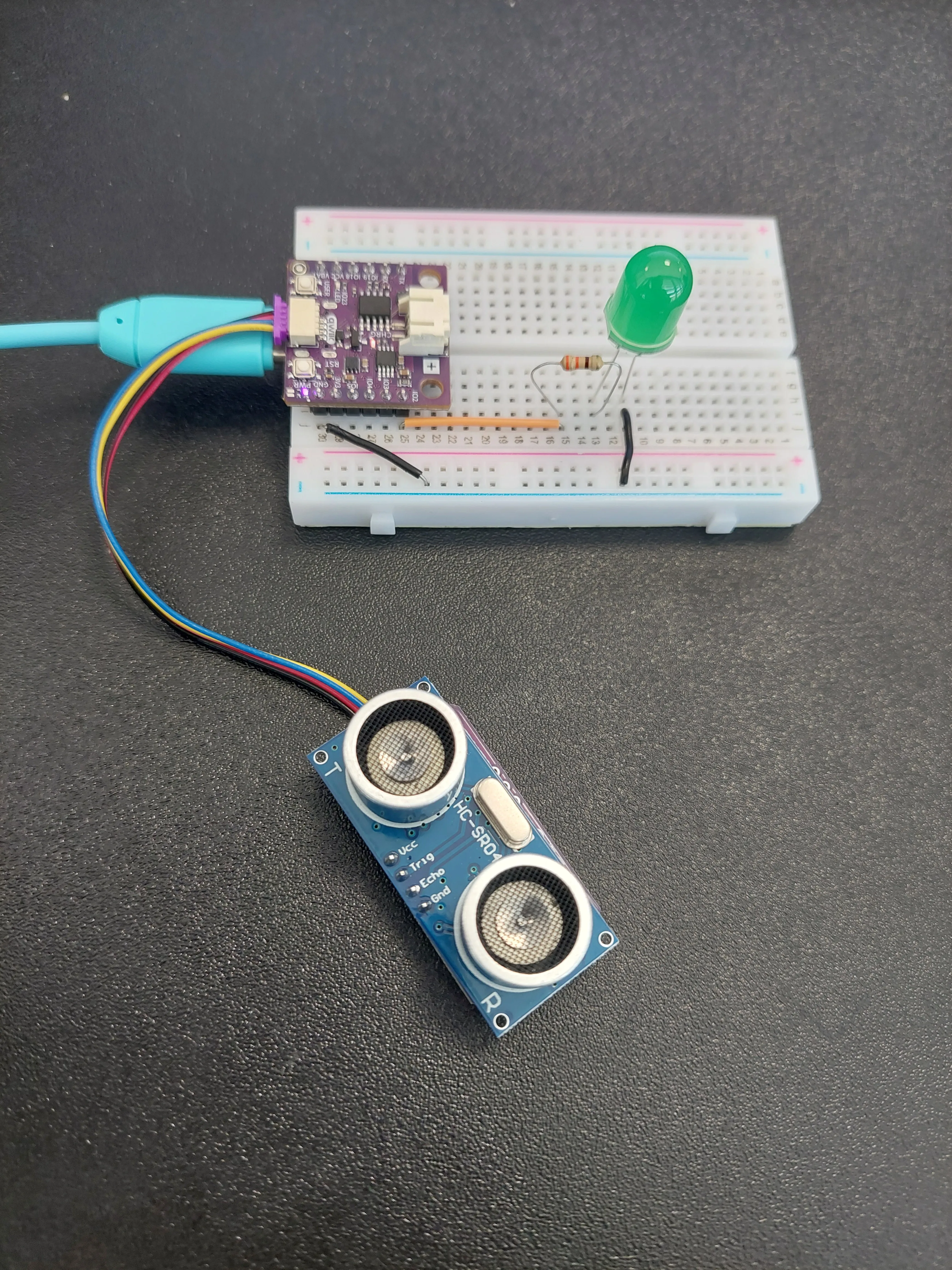
0x30 address, the same ADDR sliders left alone, and the same requirement that the two silver transducers face out into clear space. Because it talks over I2C on IO6 and IO7, which are not brought out to the pin headers, it never competes with the LED for a pin.Understanding PWM and brightness control
The NULA MINI cannot produce a voltage halfway between off and 3.3 V. What it can do is switch the pin on and off very quickly, thousands of times a second, and vary how much of each cycle it spends switched on. That fraction is called the duty cycle, and the technique is Pulse Width Modulation, or PWM.
The LED follows the switching faithfully, flicking on and off along with the pin. Your eye does not: it averages the flicker into a steady glow whose apparent brightness tracks the duty cycle.
| Duty cycle | Visual effect |
|---|---|
| 0% | LED completely OFF |
| 50% | LED at half brightness |
| 100% | LED fully ON |
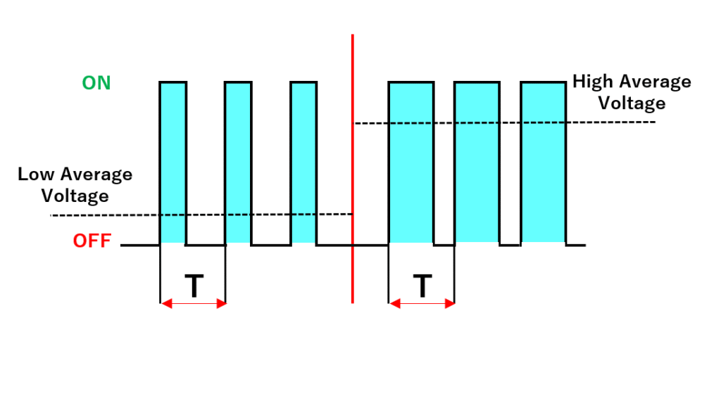
analogWrite(pin, value) is the function that sets the duty cycle. The higher the value, the longer the pin stays on in each cycle, and the brighter the LED looks.
Why the resolution has to be set first
analogWrite() needs to know what counts as "fully on". By default the board expects 8 bits, meaning values from 0 to 255, and anything larger is simply refused.
This sketch wants finer control than 255 steps, so it asks for 12 bits, values from 0 to 4095, before writing anything:
analogWriteResolution(LED_PIN, 12);
Turning a distance into a brightness
Two things have to happen between reading the sensor and writing to the pin.
First, clamping. The sketch decides it only cares about the range from 2 cm to 50 cm, and forces any reading outside that range to the nearest edge:
if (distance < MIN_DISTANCE) distance = MIN_DISTANCE;
if (distance > MAX_DISTANCE) distance = MAX_DISTANCE;
Without this, an object three metres away would produce a brightness far below zero, a meaningless value to write to a pin. Clamping guarantees the next step gets a number inside a range it was designed for.
Second, rescaling. map() takes a number from one range and stretches or squashes it into another:
int brightness = map(distance, MIN_DISTANCE, MAX_DISTANCE, 4095, 0);
Read that as: distance runs from 2 to 50; brightness runs from 4095 down to 0. The output range is deliberately backwards. A small distance lands at the high end of the brightness range and a large one at the low end, which is exactly the effect we want: closer means brighter.
Working through a few values by hand shows what the sketch will print:
| Distance | Brightness | Why |
|---|---|---|
| 2 cm or less | 4095 | clamped to the minimum, so fully on |
| 33 cm | 1451 | about a third of the way up the range |
| 39 cm | 939 | dim but clearly lit |
| 45 cm | 427 | only just visible |
| 50 cm or more | 0 | clamped to the maximum, so fully off |
Code
/**
 **************************************************
 *
 * @file        3.2_Distance_Fade_LED.ino
 * @brief       Example that shows how to control the brightness of an LED based on the distance measured by the
 *              Soldered Ultrasonic Distance Sensor. The closer an object is to the sensor, the brighter the LED
 *              becomes. This example introduces analogWrite() and map(), two functions that let us turn a measured
 *              value into a brightness level.
 *              For details, connection diagram and more, check out the example documentation at: <link placeholder>
 * @author      Soldered
 ***************************************************
 */

/*
Include the Soldered library for the Ultrasonic Distance Sensor, so we can read the distance with a single function
call instead of timing the echo ourselves.
*/
#include "Ultrasonic-distance-sensor-easyC-SOLDERED.h"

/*
Here we create our sensor object, which we named "hc". The sensor connects over easyC, which is Soldered's name for an
I2C connection over a single cable, so we pass no pin numbers: I2C always uses the same two pins on the board (IO6 and
IO7 on the NULA board) and the library already knows to look there.
*/
Ultrasonic_Sensor hc;

/*
This is a variable to which we pass the number of pin that we had connected the LED to. Because we want to dim this
LED and not only switch it on and off, we have to pick a pin that supports PWM. PWM is explained further down in
this example.
The NULA board has a pin naming logic as follows: IO2, where 2 is the number that we give to the variable.
If you wish to use a different pin, make sure you are using a IO__ marked pin.

Remember that the LED needs a 330 Ohm resistor in series with it. That resistor limits how much current flows, and
without it the LED draws more than either it or the pin is built for, so both can be damaged.
*/
const int LED_PIN = 2;

/*
These two variables define the distance range we care about, in centimeters. Anything closer than the minimum counts
as "as close as possible" and anything further than the maximum counts as "far away". Feel free to experiment with
these values.
*/
const int MIN_DISTANCE = 2;
const int MAX_DISTANCE = 50;

/*
This is how long we wait after asking for a measurement, in milliseconds. The sensor gives up listening for an echo
after 38 milliseconds, so waiting a little longer than that means the answer is always ready when we ask for it.
*/
const int MEASURE_WAIT_MS = 50;

void setup() {

  /*
  Serial.begin() establishes serial communication between your board and your computer via a USB cable. We use it
  here so we can watch both the distance and the brightness on the Serial Monitor.
  */
  Serial.begin(115200);

  /*
  pinMode() is a function that configures the specified pin to behave either as an input or in this case as an output.
  As our pin needs to light up the LED, we will put the pin in OUTPUT mode.
  */
  pinMode(LED_PIN, OUTPUT);

  /*
  analogWriteResolution() defines how many bits are used for the brightness values we write with analogWrite().
  By default the board expects 8 bits, meaning values from 0 to 255, and anything larger is simply refused. Because we
  want the finer control of 12 bits, from 0 to 4095, we have to say so here, otherwise the LED would not dim at all.
  */
  analogWriteResolution(LED_PIN, 12);

  /*
  begin() prepares the sensor for use, starting the I2C communication and telling the library which address to talk to.
  */
  hc.begin();

  //Print out the initial message so we know that the program started successfully.
  Serial.println("Distance Fade LED Example started!");
}

void loop() {

  /*
  Reading an easyC sensor takes two steps. takeMeasure() asks the sensor to send out a pulse and time the echo, and the
  wait afterwards gives it the moment it needs to finish that work and store the answer.
  */
  hc.takeMeasure();
  delay(MEASURE_WAIT_MS);

  /*
  getDistance() then fetches the stored answer, already converted into centimeters. The value comes back as a whole
  number of centimeters, which is all the accuracy this sensor can honestly offer.
  */
  int distance = hc.getDistance();

  /*
  The sensor answers with 0 when it heard no echo at all, which happens when nothing is in range or when the surface in
  front of it scatters the sound away. That is not a real measurement, so we skip the rest of this pass instead of
  treating it as an object pressed right up against the sensor.
  return ends this pass through loop() early, and because the board calls loop() again immediately we are straight back
  at the next measurement.
  */
  if (distance == 0) {
    Serial.println("No echo received, nothing in range.");
    return;
  }

  //Print the measured distance to the Serial Monitor.
  Serial.print("Distance: ");
  Serial.print(distance);
  Serial.print(" cm");

  /*
  Here we keep the measured distance inside the range we defined above. This is called clamping, and we do it because
  the next step expects a value inside a known range. Without it, an object 300 cm away would give us a brightness
  value far outside anything the LED can use.
  */
  if (distance < MIN_DISTANCE) distance = MIN_DISTANCE;
  if (distance > MAX_DISTANCE) distance = MAX_DISTANCE;

  /*
  map() is a function that takes a number from one range and rescales it into another range. Here we take the
  distance, which goes from MIN_DISTANCE to MAX_DISTANCE, and rescale it into a brightness, which goes from 4095 down
  to 0. Notice that the output range is reversed: the smallest distance gives the largest brightness, which is
  exactly the effect we want.
  */
  int brightness = map(distance, MIN_DISTANCE, MAX_DISTANCE, 4095, 0);

  /*
  analogWrite() is a function that writes an "in between" value to a pin instead of only HIGH or LOW. It does this
  using PWM, which stands for Pulse Width Modulation: the pin is switched on and off very quickly, and the longer it
  stays on during each cycle, the brighter the LED looks to our eyes.
  */
  analogWrite(LED_PIN, brightness);

  //Print the brightness value as well, so we can see how it changes together with the distance.
  Serial.print(" -> Brightness: ");
  Serial.println(brightness);
}
What you should see
Upload the sketch and hold your hand a few centimetres in front of the sensor. The LED comes up to full brightness:
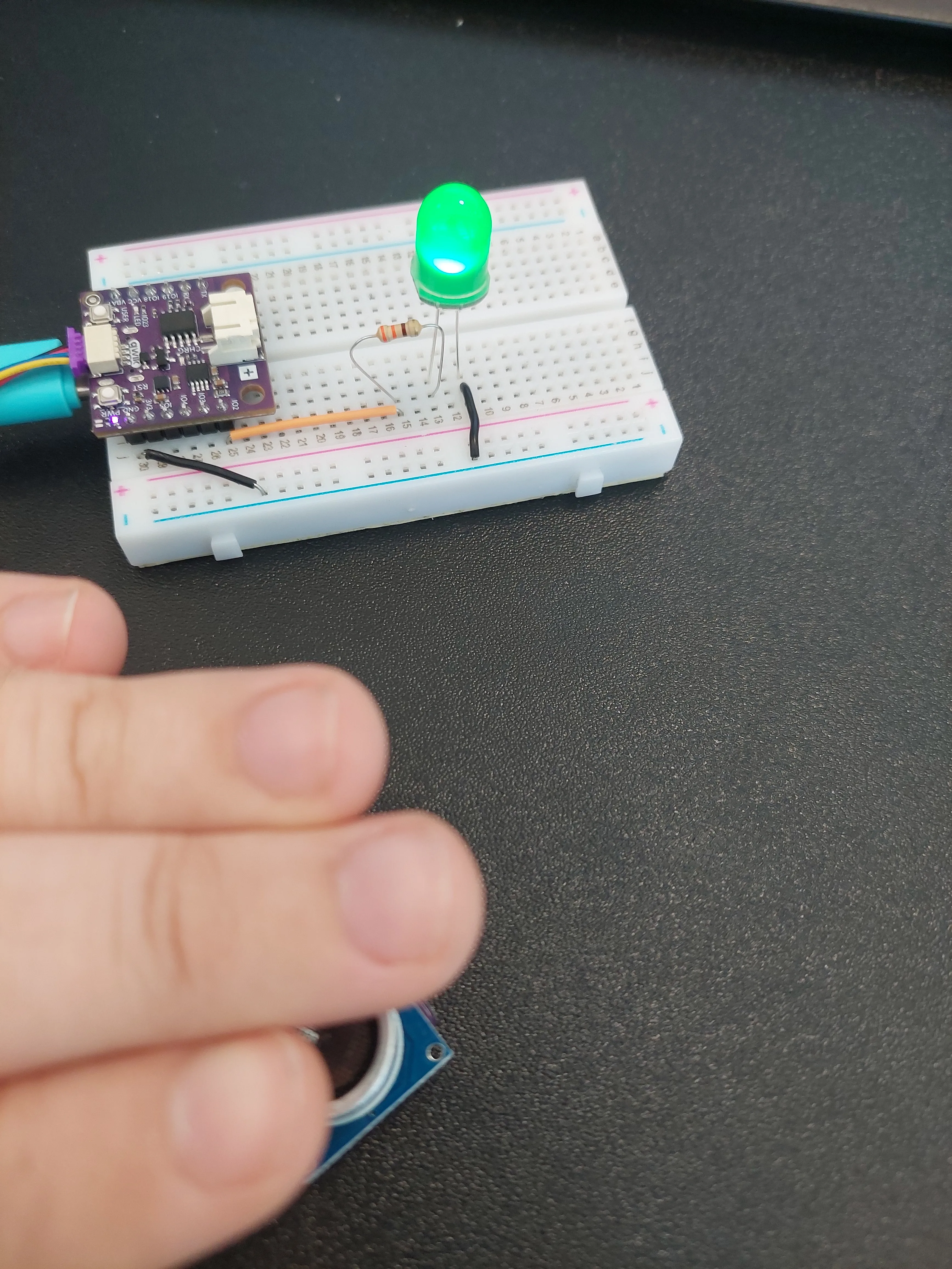
Now take your hand slowly away. The glow fades, and somewhere around half a metre it goes out altogether.
To see why, open Tools → Serial Monitor and set the baud rate to 115200. Every line carries both halves of the story: what the sensor found, and what the LED was told to do about it:

Three things are worth noticing in that output.
Most lines say Brightness: 0. Every reading of 50 cm or more clamps to MAX_DISTANCE, and 50 cm maps to zero. So the LED stays dark for 52 cm, 65 cm, 90 cm and everything beyond. It only wakes up once your hand is genuinely close. If you see nothing but zeros, you are not far from a working circuit; you are just too far from the sensor.
The LED lights suddenly, then fades gently. The first non-zero values here are 45 cm → 427 and 39 cm → 939, and 427 out of 4095 is already clearly visible. Coming in from 50 cm the LED appears to switch on rather than fade up, and the smooth part of the fade happens over the last 30 cm or so.
Readings around 1000 cm also give Brightness: 0. The lines at the top (1001, 1002, 1010 cm) are the sensor's way of finding nothing at all, as described in 3.1. They are not real distances, but clamping turns them into 50 cm anyway, so an empty room ends up looking exactly like "far away" and the LED stays off. That is the behaviour you want here, and it happens for free.
delay() at the end of loop(). The only pause is the 50 ms the sketch waits for the sensor, so readings arrive about twenty times a second and the Serial Monitor scrolls quickly. That is what makes the fade feel responsive rather than steppy. Nothing is wrong.Try it yourself: change MAX_DISTANCE from 50 to 150 and upload again. The LED now responds from a metre and a half away, but every centimetre of movement changes the brightness less, so the fade is gentler and harder to see. Drop it to 20 instead and the opposite happens: nothing until your hand is very close, then a fast, obvious sweep from dark to full. Nothing about the circuit changed. You only redefined what "close" means.
Full example
Check out the full example code on the link below:
3.2_Distance_Fade_LED.ino
Example that reads the Qwiic ultrasonic distance sensor and uses the distance to set an LED's brightness with PWM.