2.3 Photoresistor Analog Read
The goal of this example is to show you how to measure light intensity using a photoresistor (LDR) connected to one of the analog input pins on the NULA MINI board.
You'll learn how to use the analogRead() function to read a continuous range of values instead of simple ON/OFF signals.
This is your first step into analog input, essential for sensors like light, temperature, or sound sensors.
In this documentation you will learn:
- How analog inputs differ from digital inputs.
- How to connect a photoresistor to the NULA MINI board.
- How to read analog values using
analogRead(). - How to display light intensity values in the Serial Monitor.
Hardware required:
- 1x Soldered NULA MINI board
- 1x Breadboard
- 1x Photoresistor (LDR)
- 1x 10kΩ resistor
- 4x Jumper wires
- 1x USB-C cable
Putting the components together
Follow the seven steps below. Each photo is taken from the same position, so you can compare it with the previous one and see exactly what changed.
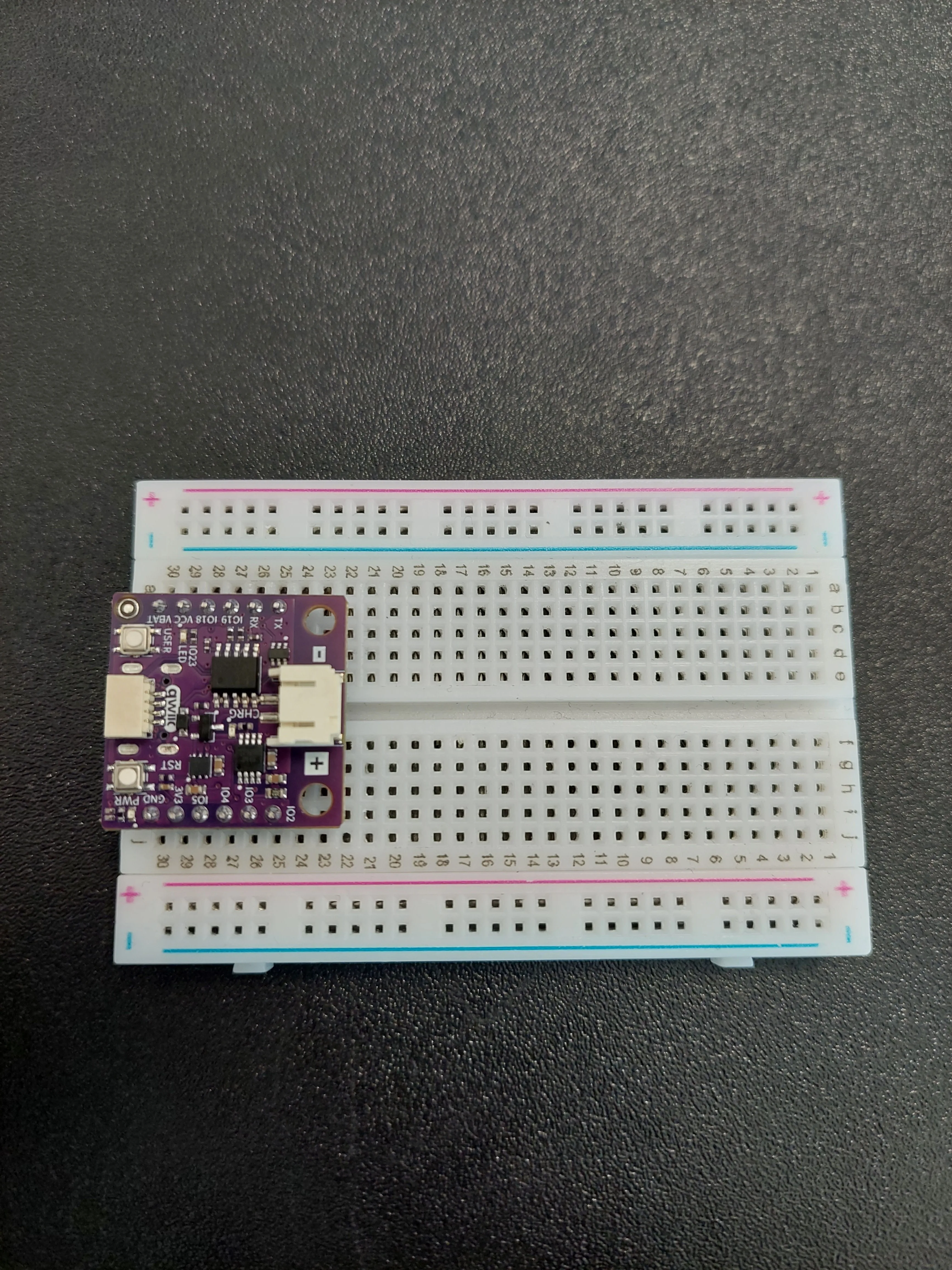
1. Insert the NULA MINI board on the breadboard
Push the board into one end of the breadboard so that its two rows of pins sit on either side of the centre channel, with the chip facing down.
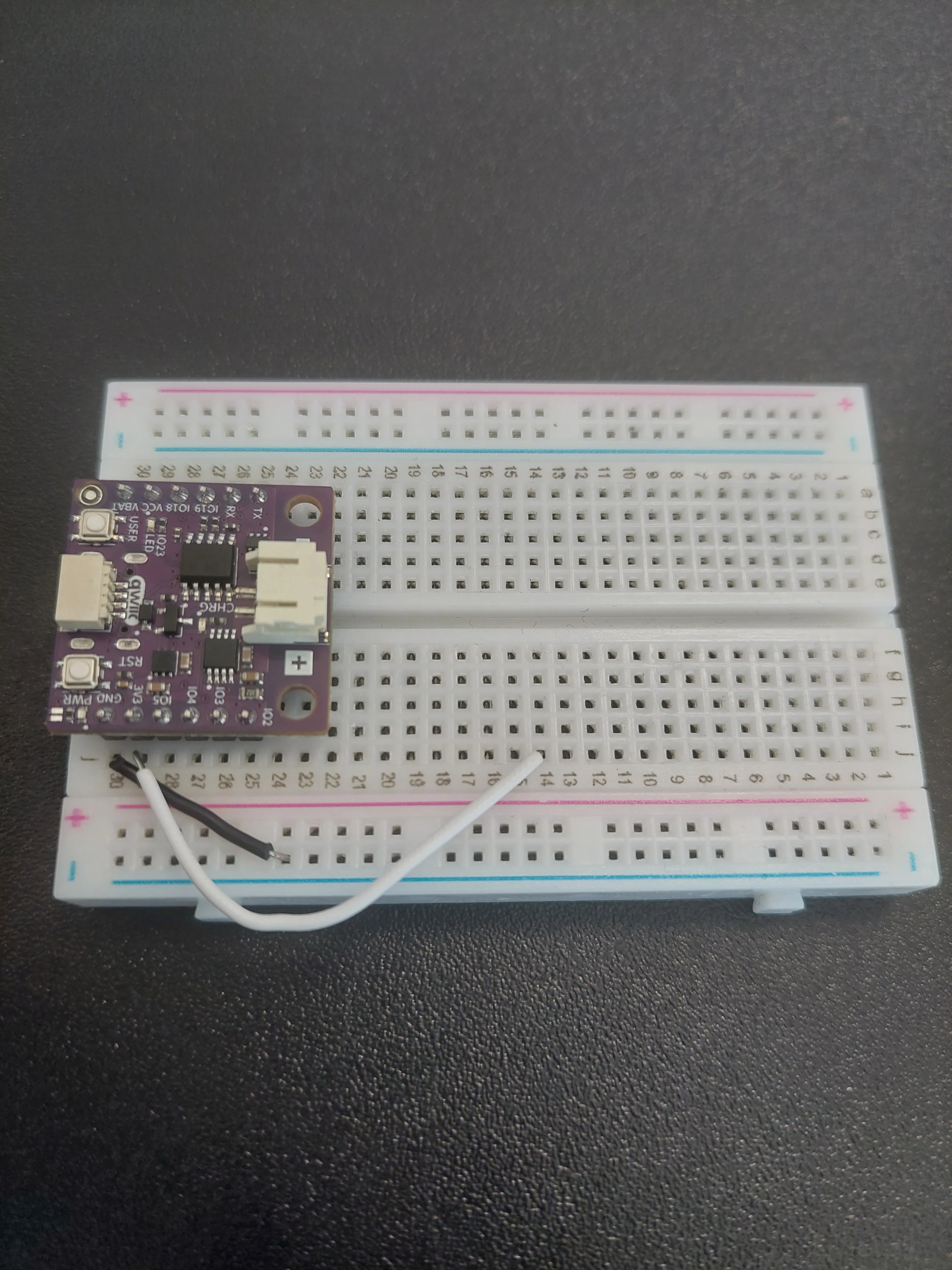
2. Bring out power and ground
Two jumpers first, so the circuit has something to sit between.
- From j30 (
GND) across to the blue − rail. That rail becomes your ground line. - From j29 (
3V3) up to row 14.
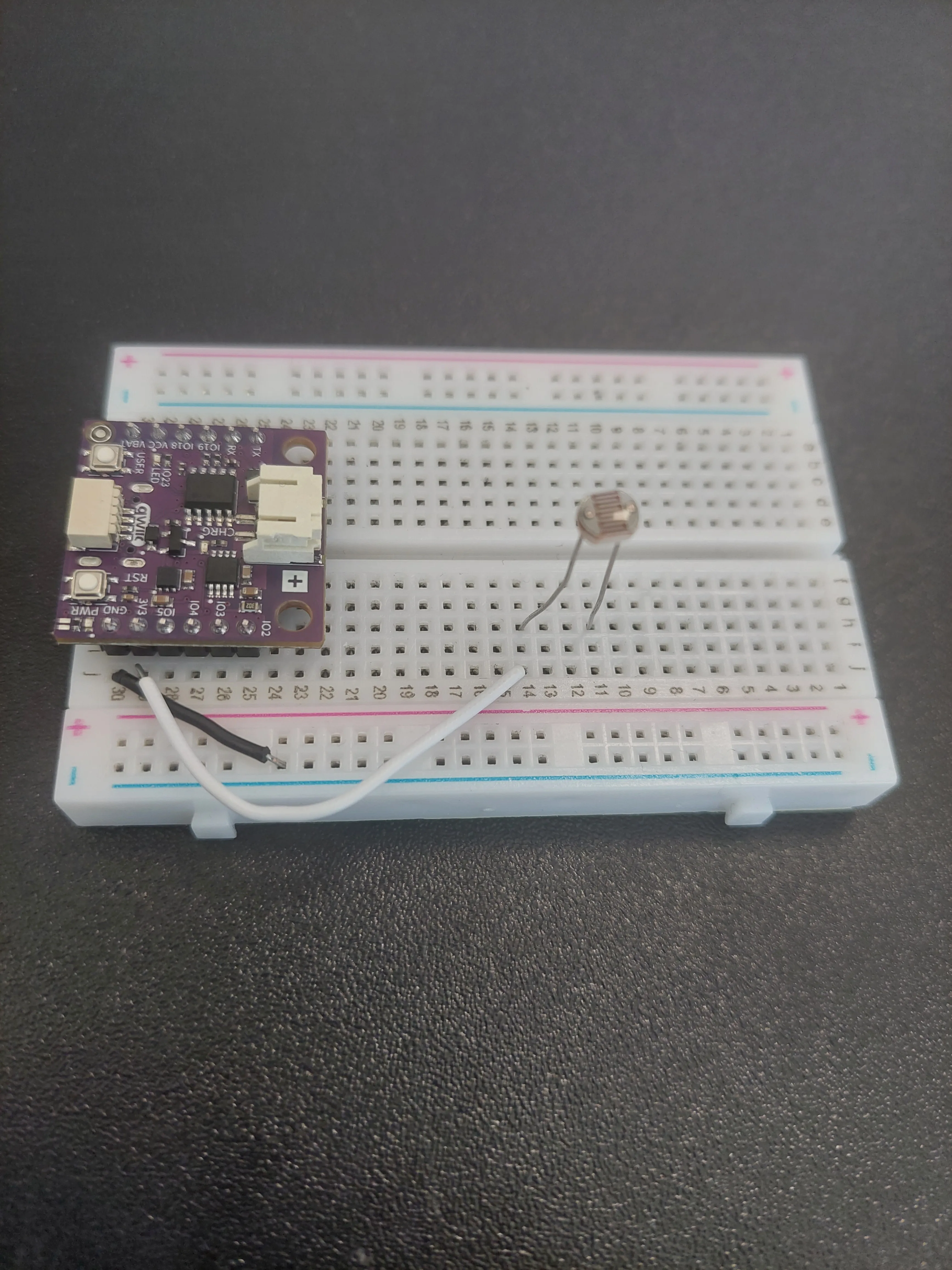
3. Add the photoresistor
The LDR bridges row 14, where 3.3 V now arrives, and row 11.
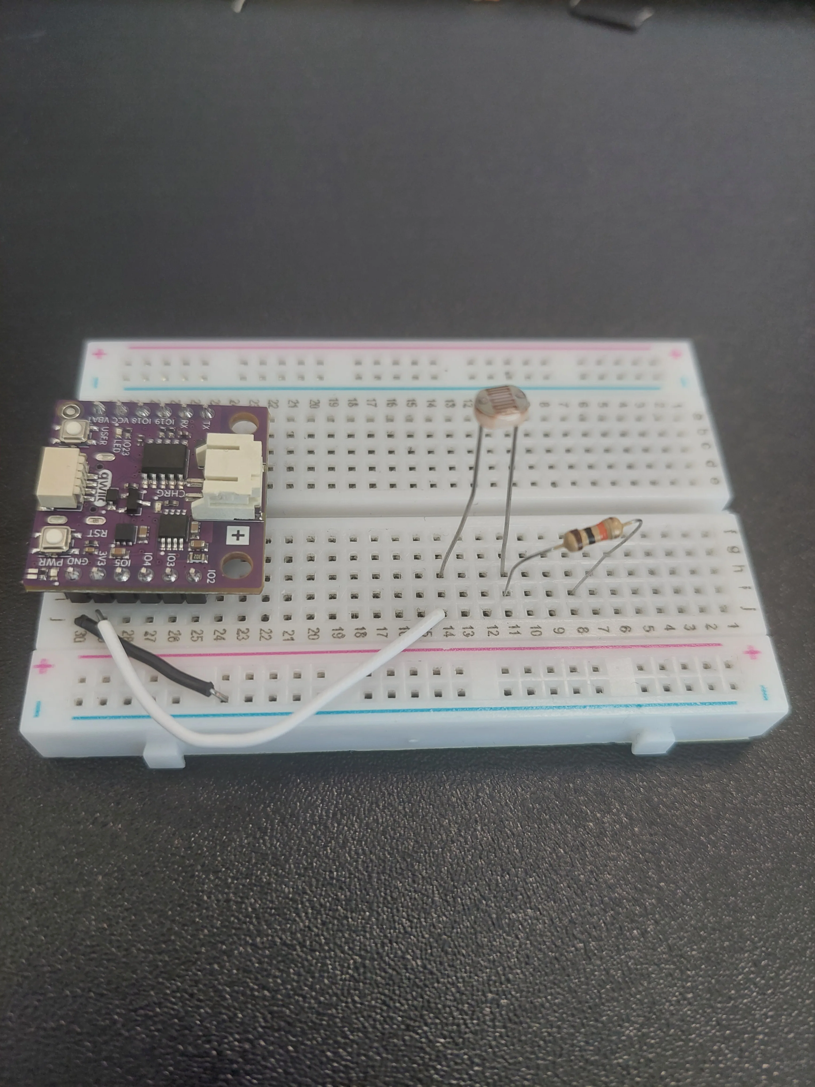
4. Add the 10kΩ resistor
The resistor continues the chain downwards: from row 11 to row 9.
5. Connect the resistor to ground
One jumper from row 9 across to the blue − rail, which is already connected to GND.
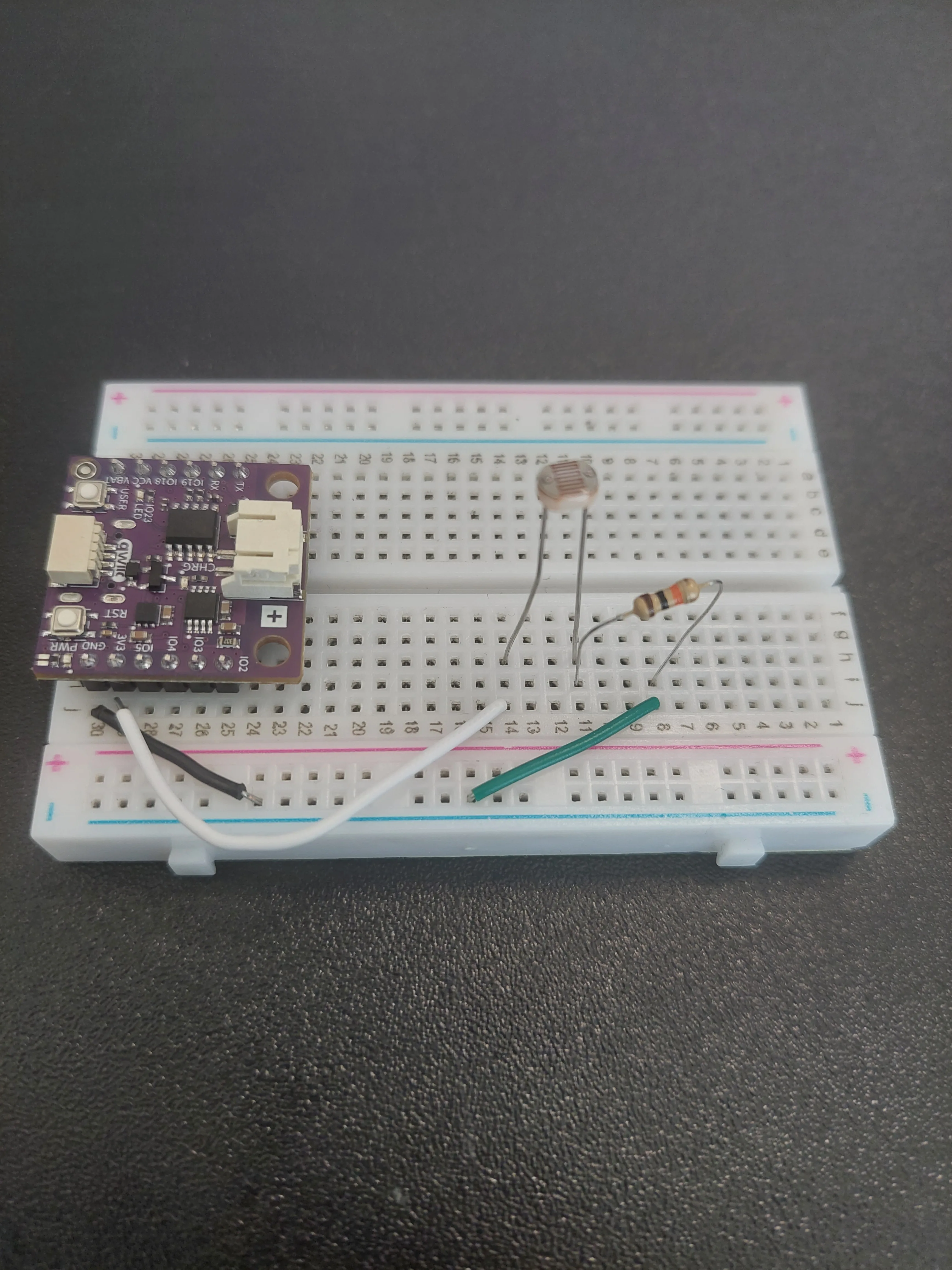
The chain is now complete: 3.3 V → LDR → 10kΩ → GND. Current flows through both parts in series.
6. Tap the middle with IO5
Now the measurement itself. Run a jumper from j28 (IO5) to row 11, the row shared by the LDR's lower leg and the resistor's upper lead.
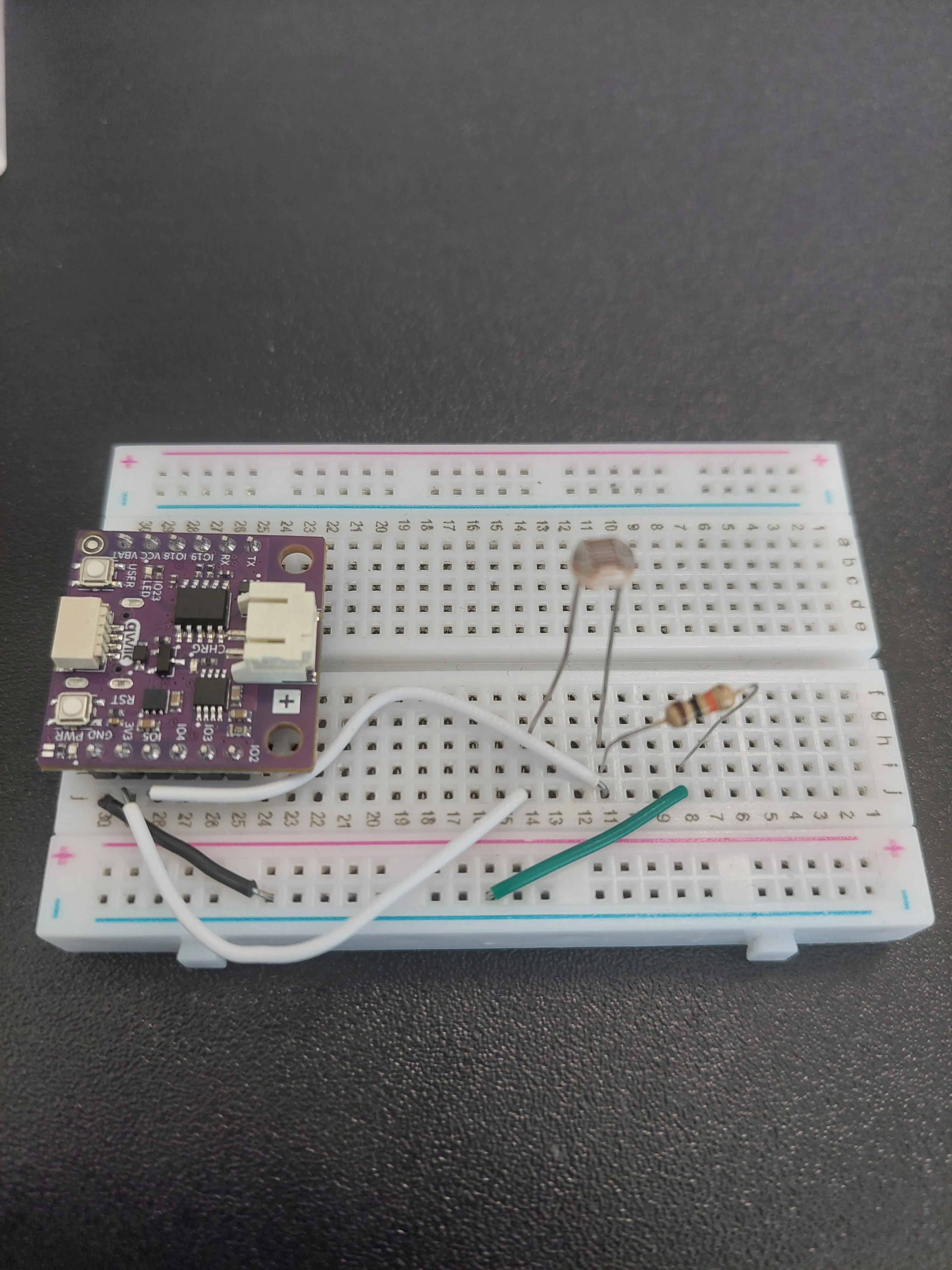
IO5 measures.7. Connect the board to your computer
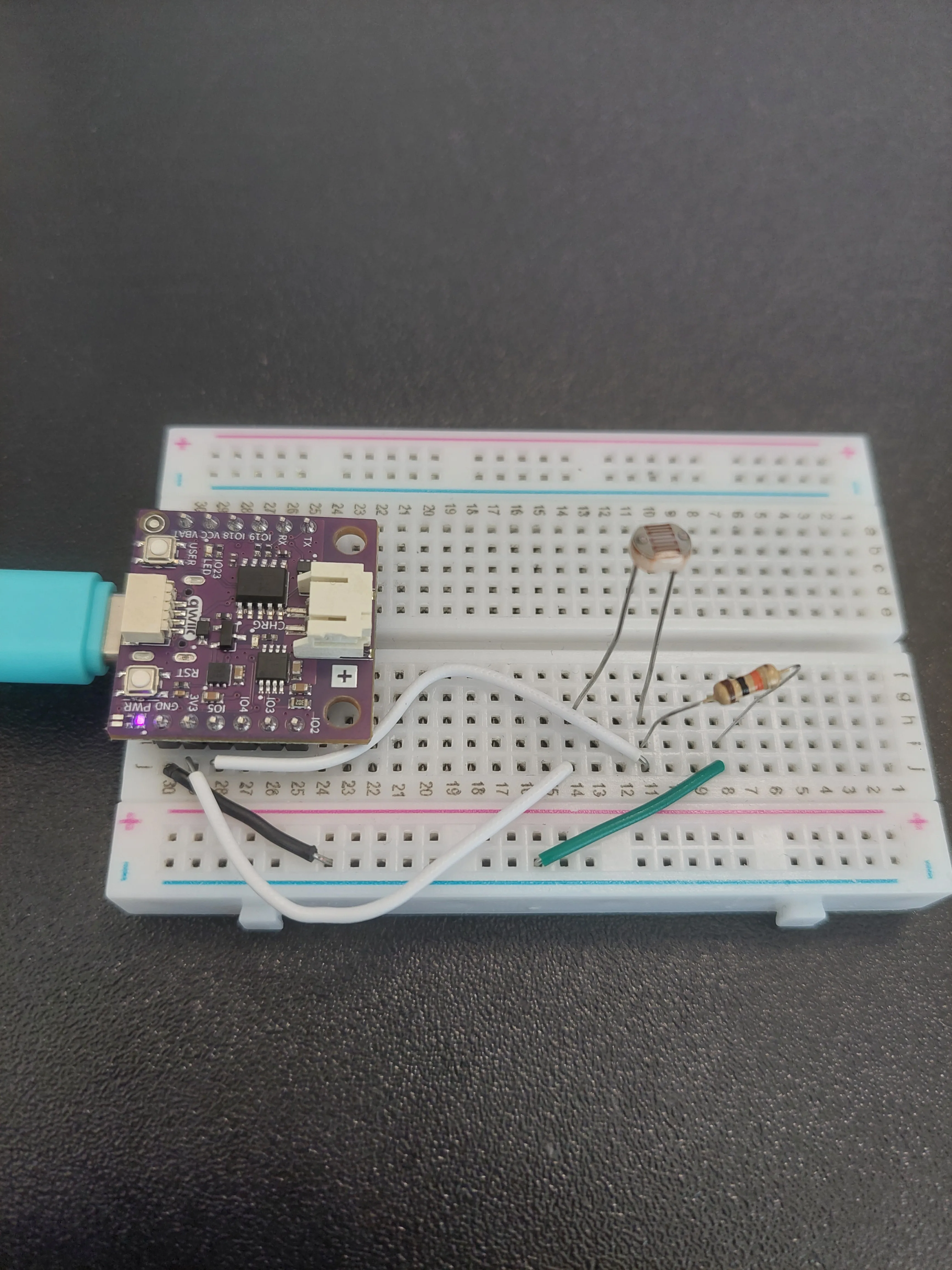
IO5 taps the row where they meet.How a voltage divider works
The board cannot measure resistance. It can only measure voltage. A photoresistor changes its resistance with light, so on its own it gives the board nothing to read.
Pairing it with a fixed resistor solves that. The two of them in series form a voltage divider, and the voltage at the point between them depends on the ratio of the two resistances:
- In bright light the LDR's resistance drops, so it keeps less of the 3.3 V for itself and the voltage at
IO5rises. - In darkness the LDR's resistance climbs, it keeps more of the voltage, and the reading at
IO5falls.
That is why the fixed resistor matters as much as the sensor: without it there is no midpoint to measure.
Understanding analog input
Unlike digital pins that only read HIGH (1) or LOW (0), analog pins can measure a continuous range of voltages between 0V and 3.3V.
The ADC (Analog-to-Digital Converter) inside the NULA MINI converts these voltages into numbers between 0 and 4095, because it uses a 12-bit ADC.
| Lighting Condition | Approx. Reading |
|---|---|
| Bright light | 3000–4095 |
| Medium light | 1500–3000 |
| Dark | 0–1500 |
Code
/*
This is a variable to which we assign the number of the pin that we connected the photoresistor's output to.
The NULA MINI board uses analog-capable pins (ADC pins) to read varying voltages.
In this example, we will use IO5, which supports analog input.
*/
const int LDR_PIN = 5;  // Analog input pin for photoresistor

/*
This variable will store the raw analog value read from the sensor.
Since the NULA board uses a 12-bit ADC, the returned value will range from 0 to 4095.
*/
int lightValue = 0;

void setup() {

  /*
  Serial.begin() starts serial communication between the board and the computer.
  We use it to display the measured values on the Serial Monitor.
  */
  Serial.begin(115200);

  /*
  analogReadResolution() defines how many bits are used for ADC readings.
  The NULA MINI supports 12-bit resolution, which means analogRead() returns values from 0 to 4095.
  */
  analogReadResolution(12);

  /*
  Print a startup message to confirm that the program is running.
  */
  Serial.println("Cover or shine light on the sensor to see value changes...");
}

void loop() {

  /*
  analogRead() reads the voltage at the given analog pin and converts it into a digital number.
  The higher the light intensity, the lower the resistance of the photoresistor, and the higher the voltage read.
  */
  lightValue = analogRead(LDR_PIN);

  /*
  Print the measured value to the Serial Monitor.
  */
  Serial.print("Light level: ");
  Serial.println(lightValue);

  /*
  Add a short delay so the readings are easier to observe.
  */
  delay(500);
}
What you should see
Upload the sketch, then open Tools → Serial Monitor and set the baud rate to 115200. A new reading appears twice a second.
Now put your hand over the sensor and watch the numbers drop.
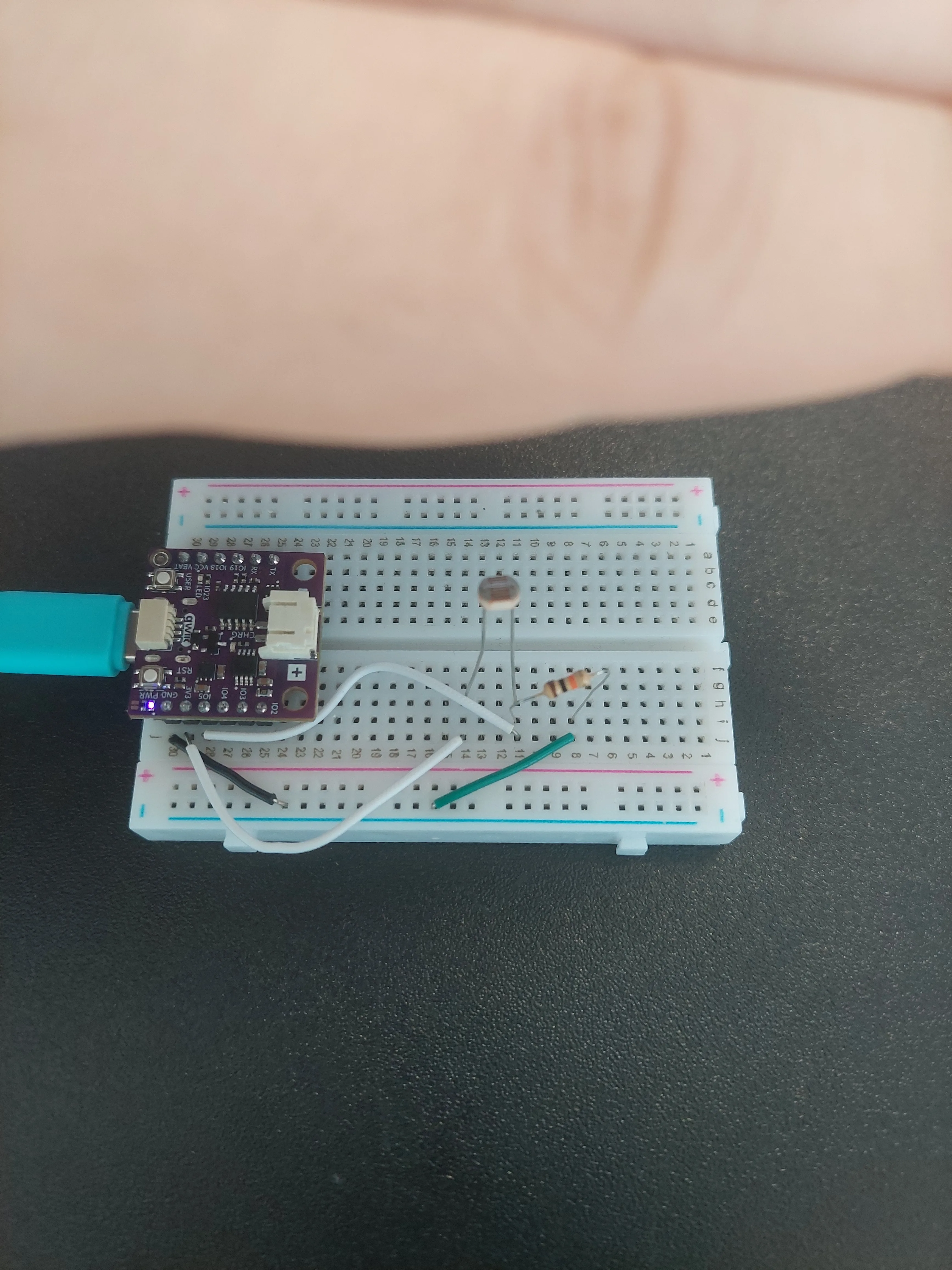

IO5 really is tapping the junction row and not one of the outer rows.Full example
Check out the full example code on the link below:
2.3_Photoresistor_Analog_Read.ino
Example that shows how to read analog values from a photoresistor and display light levels on the Serial Monitor.